1. Background
Operating the dialysis apparatus during hemodialysis treatment is an important procedure linked to patients’ lives. However, it is currently impossible to acquire appropriate operating techniques outside of clinical settings. In fact, the Japanese society for dialysis therapy reported in 2001 that there were 372 cases of serious accidents that occurred during dialysis due to the lack of experience of the dialyzer operators. This was attributed mainly to the lack of opportunities for proper training.
One approach for eliminating these accidents is the development of a system that allows the following: 1) the simulation of high-risk accidents (abnormal situations; Table 1) that frequently occur during dialysis treatment, 2) trainees to experience these simulations of accidents that can occur quite suddenly, and 3) trainees to acquire basic operating techniques for troubleshooting accidents outside of clinical settings.
| Contents | Valuesa |
|---|---|
| Needle came offb | 94 (25.3) |
| Blood circuit disconnectb | 60 (16.1) |
| Filtration failure | 50 (13.5) |
| Mixed air | 39 (10.5) |
| Puncture failureb | 29 (7.8) |
| Medication failure | 24 (6.5) |
| Dialysate failure | 19 (5.1) |
| Hemodialysis cancellation | 16 (4.3) |
| Downfall | 10 (2.7) |
| Hemostasis failure | 7 (1.9) |
| Hospital infection | 3 (0.8) |
| Others | 21 (5.7) |
aValues are expressed as No. (%).
bPertinent data of simulator.
Currently, the existing hemodialysis simulator systems (operation training, educational) include computer-based simulation/training programs (1), dialysis puncturing technique training simulators (2), and dialysis patients’ resuscitation simulators (3). Of the simulation tools that use actual dialysis apparatus, the training tool that we developed uses simulation modules with a circulation system that simulates accidents (4-6). There are other operation training simulation systems for extracorporeal circulation; these are used for training related to pump-oxygenators during heart surgeries (7-10). However, there is no system that allows the use of actual clinically-used dialysis apparatuses with a simulated blood circuit, trainees to experience operation methods, and appropriate measures to be taken in the case of accidents.
In response to this gap, we developed a prototype consisting of the following features that allow: 1) the set-up of a circulation system with existing dialysis machines of different models and blood circuits, 2) training based on the five most common scenarios in a clinical setting, which has the highest patient risks (Box 1), 3) control and adjustment so that it can be reproduced on the circulation simulator, and 4) production of an alarm corresponding to these scenarios by the dialysis apparatus.
| Apparatus Message = Actual Accident |
|---|
| Venous pressure lower limit alarm = Draw blood poor flow |
| Venous pressure lower limit alarm = Dialyzer clotting |
| Venous pressure lower limit alarm = Return blood circuit disconnect |
| Venous pressure upper limit alarm = Return blood circuit clotting |
| Blood leak alarm = Blood leak |
2. Objectives
The dialyzers used in Japan are variable, and we were unable to control the existing circulation systems on the non-standardized dialysis machines. This universality is what was missing from the existing systems. Therefore, the task was to develop a universal circulation system compatible with the dialysis machines of various models or manufacturers.
In the present research, we took five models of dialysis apparatus by four different manufacturers that are most commonly used in Japan and sought to develop a system that will allow the present circulation system to appropriately control each apparatus. Thus, we would be able to use the mentioned circulation system on each of the dialysis machines, enabling simulation training in various institutions.
3. Materials and Methods
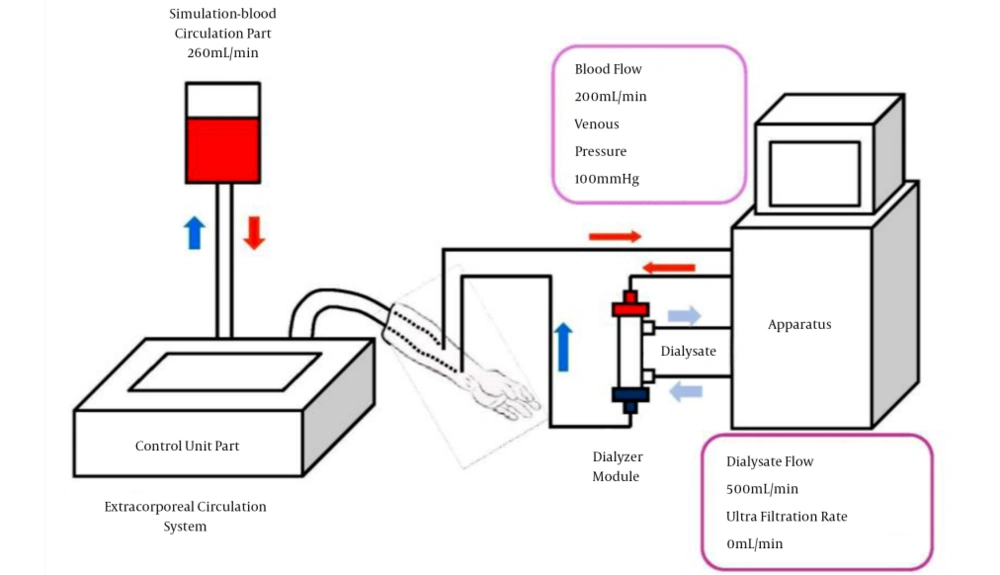
After the initial set-up of the blood circuit, it was connected to the circulation system of the five models of apparatus: DBG®-03, DBB®-100NX (Nikkiso Co., Ltd. Tokyo, Japan), TR®-3000S (Toray Medical Co., Ltd. Tokyo, Japan), NCV®-10 (Nipro Co., Ltd. Osaka, Japan) and SD®-300 (JMS Co., Ltd. Osaka, Japan). To conduct this experiment, general treatment conditions (i.e., operation of the dialysis apparatus under normal conditions) were set, which consisted of blood pump flow rate at 200 mL/min, dialysate solution flow rate at 500 mL/min, ultrafiltration volume at 0 mL/min, and circulation system pump flow rate at 260 mL/min (Figure 1). The circulation system was embedded with four proportional solenoid valves (hereinafter, V1 - V4), so the valve opening value (hereinafter, parameter value) to differentiate the conditions of normal simulation and accident simulation was determined. This parameter value would serve as the index of the circulation system’s control.
The alarm point of the dialysis apparatus during accident simulation varied according to each manufacturer; therefore, the default setting for all models was used for the purpose of this experiment.
This experiment was conducted with the following two objectives: first, to test whether the dialysis apparatus raised the alarm in response to the circulation system’s control, second, the time lapse between the start of the operation (i.e. turning on the dialyzer connected to the circulation system) to the desired alarm activation was measured 20 times, and the average time was calculated to evaluate the degree of compatibility of the system with various dialysis apparatus models.
3.1. Components of the Extracorporeal Circulation System
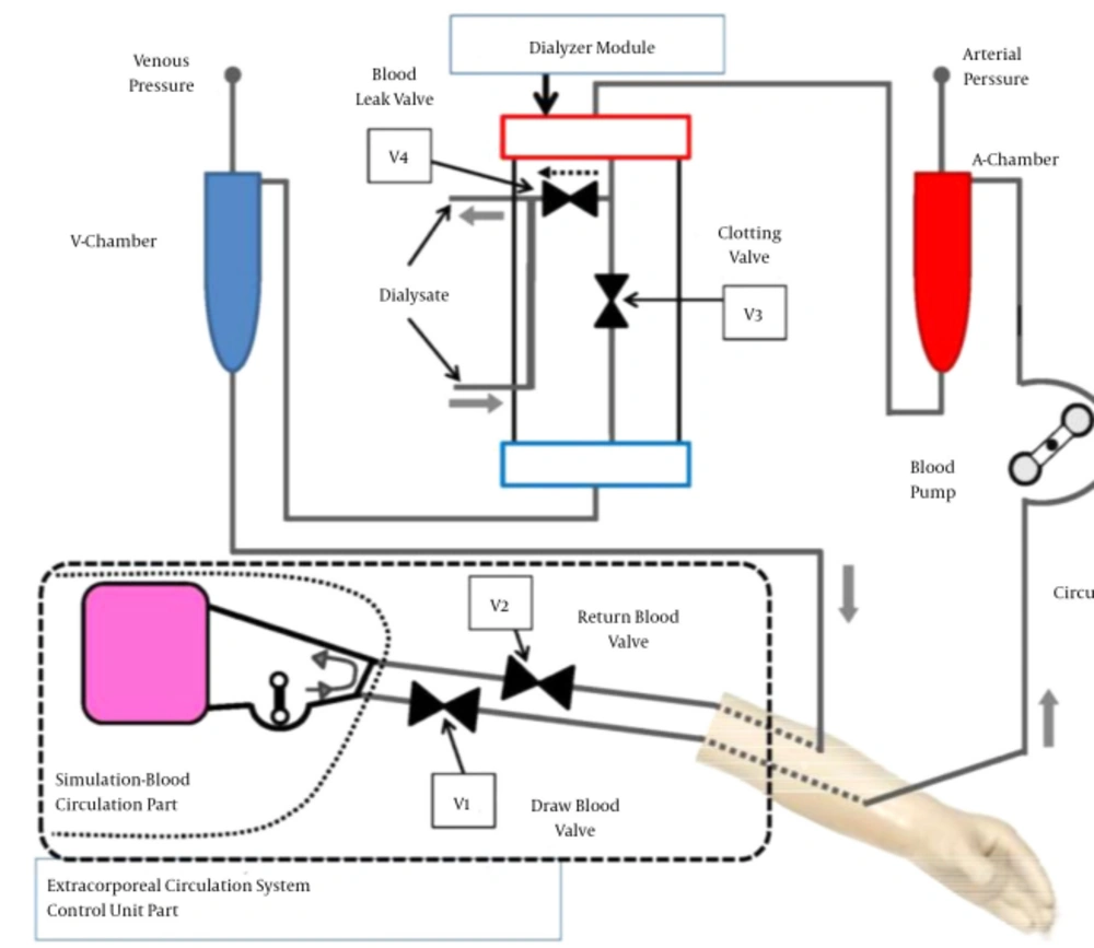
The circulation system composed of the arm portion, the control unit, and the dialyzer module (Figure 2).
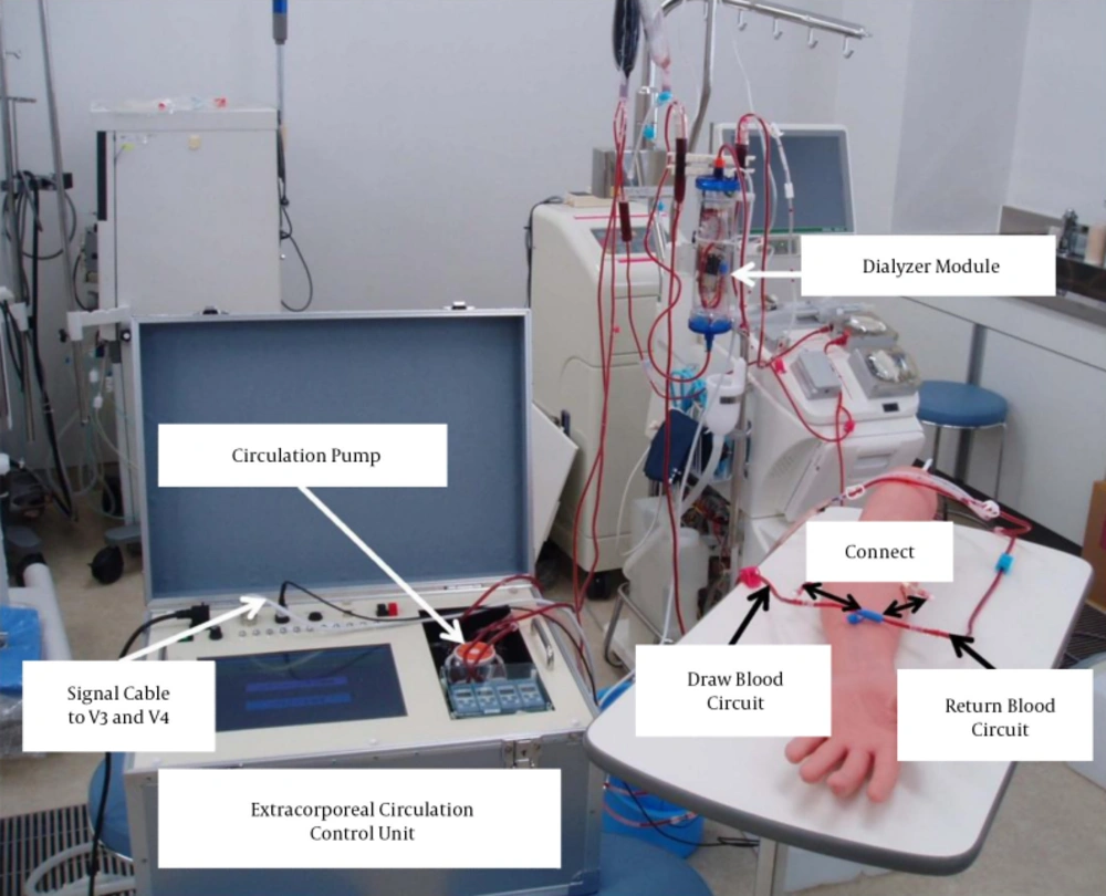
The arm portion is connected to the blood draw and blood return circuit to feed the artificial blood from the circulation system into the blood circuit. The dialyzer module is connected to the arterial and venous sides of the blood circuit, as well as the dialysate solution circuit. Finally, the blood pump, arterial and venous blood pressure monitor circuits, etc., are attached to the dialysis apparatus to complete the set-up of a model that simulates the clinical situation (Figure 3).
The opening and closing of the proportional solenoid valves (V1 - V4) allow flow control of the circulation system, which produces the alarm for the specific accident in the five simulation scenarios. The accident can be manually selected by the operator using the control unit. The control signal was programmed using the programming software Visual basic®2010 (Microsoft Co., Ltd. USA) so that it delivers signals to V1 - V4 to adjust the degree of opening or closing based on the parameter value.
When the control signal is sent to each of the solenoid valves V1 and V2, inside the control unit and V3 and V4 in the dialyzer module, the blood circuit’s pressure and flow can be suddenly changed by modifying the degree of opening of the valves, which simulates an accident that then triggers the follow-up alarm.
3.1.1. Control Unit
The bypass circuit is set to circulate the simulation blood. The circulation pump inside the control unit circulates the simulation blood. Setting the simulation blood flow rate at 260 mL/minute allows blood flow to be supplied via the arm portion, according to the patient blood inflow volume during a general dialysis treatment (blood pump volume of the dialysis apparatus) of 200 mL/minute, thus making the extracorporeal circulation that simulates a treatment scenario possible.
The control unit is composed of the circulation pump that adjusts the circulation volume of the simulation blood, proportional solenoid valves (V1 and V2) that control the simulation blood volume control of the blood removal/blood re-transfusion outlet portions, the controller, which sends control signals to V3 and V4 inside the dialyzer module, and a computer that is programmed to control the above. Closing the V1 valve allows simulation of the “draw blood circuit poor flow” accident. Opening the V2 valve wider than the normal degree of opening simulates the “return blood circuit disconnect” and closing it simulates the “return blood circuit clotting.” Closing V3 simulates the “dialyzer clotting” and opening V4 simulates the “blood leak.” The control of valves V1 - V4 and the circulation pump is done using the computer, which is programmed so that the pressure value and extracorporeal circulation blood flow volume can be regulated as the parameter value at this time to act as the simulation of the clinical situation.
3.1.2. Dialyzer Module
The V3 and V4 (Figure 2) are embedded and housed inside the dialyzer housing to connect the blood circuit and the dialysate liquid circuit to separately circulate the simulation blood and dialysate liquid for simulating a treatment situation. The control unit sends control signals to these two solenoid valves to simulate the aforementioned accidents.
4. Results
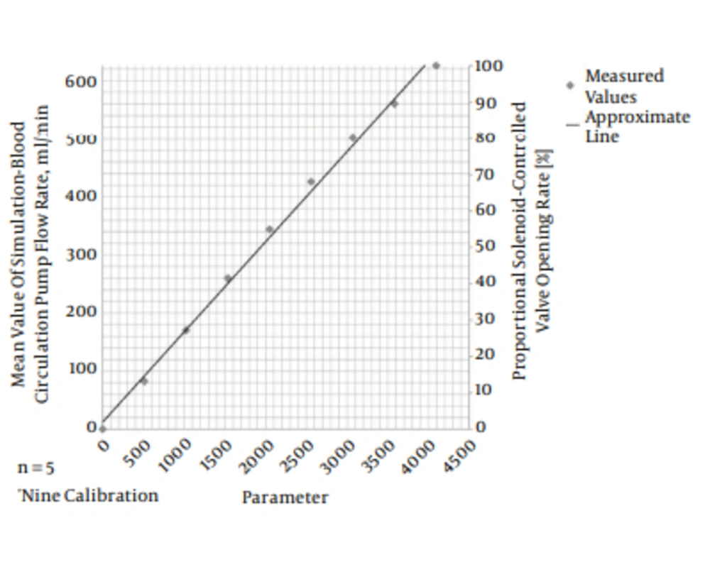
A calibration curve of the relationship between the circulation pump flow rate (0 - 600 mL/minute) and the parameter values was drawn (Figure 4) to determine the parameter values of the proportional solenoid valves as shown below so that the pressure value of the blood circuit at normal operation and in an abnormal (alarm) situation could be simulated.
For the parameter values of 0 - 4095, the opening degree of the solenoid valve was set at 0% - 100%. 1) Extracorporeal circulation pump flow rate (1500 = 260 mL/minute). 2) V1 (normal: 4095 = 100%; blood removal deficit: 150 = 4%). 3) V2 (normal: 2500 = 61%; blood return circuit clotting: 1500 = 37%; blood return circuit disconnect: 4095 = 100%). 4) V3 (normal: 4095 = 100%; dialyzer clotting: 1500 = 37%). 5) V4 (normal: 0 = 0%; blood leakage: 4095 = 100%).
We succeeded in activating the alarm related to each of the five accident scenarios in the dialysis apparatus of all five models (Box 1).
The average time to achieve the activation of the alarm is shown in Table 2. The time it took to activate the dialysis apparatus’s messages (indicating an accident) were as follows: 1) decreased arterial or venous pressure (blood removal deficit) 5 to 7 seconds; 2) decreased venous pressure (re-transfusion line detachment): 6 to 8 seconds; 3) increased venous pressure (re-transfusion line obstruction): 5 to 7 seconds; 4) increased arterial pressure or decreased venous pressure (dialyzer clotting): 2 seconds; and 5) blood leakage (blood leakage): 10 to 19 seconds. As such, we were able to achieve the alarms for all the above scenarios that can happen in a treatment setting in all the five models under 20 seconds.
| Valve Number | Alarm Message | Apparatus | ||||
|---|---|---|---|---|---|---|
| DBG®-03 | DBB®-100NX | TR®-3000s | NCV®-10 | SD®-300 | ||
| V1 | Venous pressure lower limit | 6 ± 0.4 | 5 ± 0.4 | 6 ± 0.4 | 7 ± 0.4 | 5 ± 0.3 |
| V2 | Venous pressure lower limit | 6 ± 0.6 | 6 ± 0.4 | 7 ± 1.2 | 8 ± 0.8 | 6 ± 0.4 |
| V2 | Venous pressure upper limit | 5 ± 0.2 | 5 ± 0.5 | 5 ± 0.6 | 7 ± 0.5 | 6 ± 0.4 |
| V3 | Venous pressure lower limit | 2 ± 0.3 | 2 ± 0.3 | 2 ± 0.2 | 2 ± 0.4 | 2 ± 0.2 |
| V4 | Blood leak | 10 ± 0.9 | 10 ± 0.5 | 10 ± 0.9 | 19 ± 1.5 | 12 ± 1.1 |
5. Discussion
Our results demonstrate that manipulating the control function of the circulation system allowed the simulation of normal operation and five alarm (accident) scenarios in all five dialysis apparatus. That is because none of the manufacturers have revealed the algorithm behind the set-off of the alarm in their dialysis apparatus models. Although it was dependent on the dialysis apparatus, each alarm was between one and two seconds in duration, and since sampling was done more than 10 times, this can be assumed to be displayed from their mean value. Therefore, sometimes the reaction occurred as early as two seconds. In other cases such as the blood leakage alarm, however, it took longer because this was detected by the sensor in the apparatus after the signal of the blood leakage passes through the dialysate liquid line, which extends 100 cm from the dialyzer outline opening.
Based on the above and given the fact that the upper and lower pressure limit alarms were activated within 20 seconds, we can assume that the parameter value setting was correct and the control was made possible.
Based on this, we can state that this circulation system has high compatibility and is an accident simulation-type simulator system that can be used on many different dialysis machines. However, as seen in Table 2, the value for blood leak is markedly higher than the other values at 19 seconds. Thus, this is an important point that must be verified by observing whether the sensor was clean and if the zero point was properly aligned, etc. In the next step of this research, simulation training, using this system should be conducted to test its effectiveness.
5.1. Conclusions
A simulator system using an extracorporeal circulation system to simulate a clinical hemodialysis situation and common accidents was developed and its compatibility with various dialysis apparatus was evaluated.
The accident-to-alarm system studied on the five dialysis apparatus in the five chosen scenarios was simulated successfully:
Draw blood poor flow: venous pressure lower limit
Return circuit disconnect: venous pressure lower limit
Return circuit clotting: venous pressure upper limit
Dialyzer clotting: venous pressure upper limit
Blood leakage: blood leakage.
Since the compatibility with different models of dialyzers was also successful, we believe that it is possible to set it up in many dialysis facilities across Japan.
In the next phase of our experiment, simulation training using this system will be conducted to test its effectiveness.


