1. Background
Ultrasound is an effective, non-invasive, and affordable imaging modality, which is used in almost all areas of clinical practice. In conventional ultrasonography, the ultrasound image is not labeled with information on the location or orientation of the transducer. There is also no information on which body parts are under examination. Although this modality is implemented variedly in different countries, ultrasound image without body mark may be interpreted differently from the operator's intention, or it may be interpreted according to the operator's intention differently from the information in the image; therefore, they may lose their objective value.
In clinical practice, knowledge of the transducer location and orientation may not be necessary, as standard views are widely applied in ultrasounds (1); these standard views have been optimized for differentiating normal findings from abnormal ones. However, accurate information on the transducer location and orientation can be important in ultrasounds if there is a lack of anatomic landmarks to estimate the imaged body part, or when information is needed regarding the transducer or the patient’s posture changes. To overcome these problems, annotation using a body mark or text is essential. However, this approach has a disadvantage, as the operator needs to spend additional time and effort to use various control buttons. Besides, the ultrasound examination site intended by the operator and the body mark may not exactly match, and there may be errors during the manipulation process.
Several methods have been developed to install equipment that enables three-dimensional (3D) position calculation as a supplement for the existing body mark system of ultrasounds (2-4). These methods involve installing equipment on the ceiling of the ultrasound room or the probe itself, as well as a tracking system, which can monitor the device position within a subject and superimpose a graphic symbol on the diagnostic image. However, these methods require the transducer to have additional hardware, such as a gyro sensor and an acceleration sensor, which can be difficult to apply in clinical practice.
In the present study, we devised a novel technology that minimizes the need for additional hardware and intuitively provides information on the ultrasound location in a conventional ultrasound image. This technology was designed for use in various organs to record the transducer position relative to the body. It utilizes a 3D depth camera, which can acquire images of the inspection site, with the transducer and software specifically designed to merge the acquired image with the conventional ultrasound. This technology was experimentally applied to abdominal ultrasounds as one of the most frequently used types of ultrasounds.
2. Objectives
This pilot study aimed to investigate the accuracy of image interpretation and the effectiveness of body navigation-loaded ultrasounds, including the real-time transducer location and inspection site, compared to conventional ultrasounds.
3. Patients and Methods
3.1. Study Population
After obtaining approval from the institutional review board, a total of 29 healthy adult participants were prospectively enrolled in this study through in-hospital recruitment, according to the World Medical Association Declaration of Helsinki. Informed consent was obtained from all the participants. Besides, consent to publish the acquired body navigation-loaded ultrasounds was obtained from the participants. From December 2018 to January 2019, one gastrointestinal radiologist performed the abdominal ultrasounds of various organs for the participants, with or without NPO (nothing by mouth) for their convenience.
3.2. Concept of Body Navigation-loaded Ultrasound Acquisition Technology and Technical Considerations
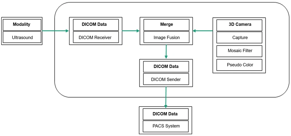
The technology devised in this study used a commercial 3D depth camera to capture the ultrasound scene in the patient’s vicinity as the operator acquired a conventional ultrasound image. The images including the inspection site and transducer location were combined in real time in the form of thumbnails and integrated into conventional ultrasound images, using a commercial computer and gateway system (5) with a 3D mesh filter (6); they were then automatically transmitted to the picture archiving and communication system (PACS) server (Figure 1).
The developed body navigation-loaded ultrasound technology did not require highly advanced skills or equipment. However, there were some issues that needed to be addressed during its design and development. The first issue was to protect the patient’s privacy (e.g., face or breasts). We aimed to minimize the exposure of sensitive organs by applying a 3D mesh filter while maintaining the shape, size, and ratio of the body according to the 3D depth camera. The 3D depth camera enabled using an object recognition function that could not be implemented with a normal camera; therefore, the body could be animated. Additionally, the location of the transducer could appear as it was without modification. Overall, the results provided a more intuitive understanding of navigation-loaded ultrasound images.
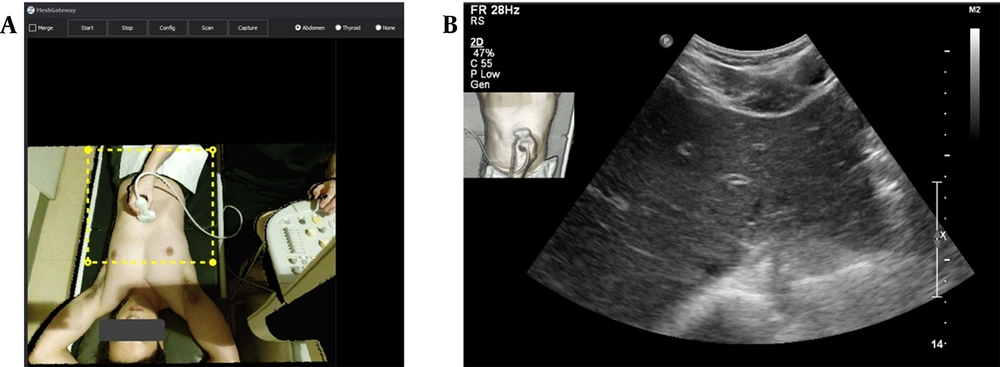
The second issue was determining how to simultaneously acquire ultrasound images and 3D depth images to increase the operator’s convenience. Since it was not efficient to separately use the ultrasound image acquisition button and the camera capture button, the camera was set to capture an image when the ultrasound image acquisition button was pressed, using the Mesh Gateway software on a computer connected to an ultrasound system. Our developed Mesh Gateway software included the Ultrasound Navigation Image Convergence System. Therefore, the navigation-loaded image could be transmitted directly to the PACS server (Figure 2).
The ultrasound navigation convergence system (Mesh Gateway) work screen and the navigation-loaded ultrasound image transmitted to the picture archiving and communication system (PACS). A, The image acquired by the three-dimensional depth camera, installed on the participant's head, is transmitted to the Mesh Gateway system and appears on the work screen. Only the yellow dashed box is used for image fusion, which can be adjusted according to the patient's position or inspection site. B, A navigation-loaded ultrasound image taken by a transverse scan of the left hemi-liver. The top left side of the image shows a thumbnail containing information on the inspection site and transducer.
The third issue was determining the extent of the inspection site and transducer information that needed to be included in the ultrasound image acquired with a 3D depth camera. With the camera fixed above the patient's head, body parts other than the inspection site were cropped. Adjustments were required before the ultrasound examination so that the inspection site and the transducer location would not deviate from the cropped area. The next step was to determine where to place the navigation-loaded image on the conventional ultrasound image. Care was taken not to have overlapping information regarding the ultrasound parameters or scanned ultrasound images. Depending on the ultrasound machine manufacturer and model, the selected place for the thumbnail is expected to be variable; however, we preferred to insert the thumbnail in the upper right part of the ultrasound image.
3.3. Ultrasound Protocol and Acquisition of Navigation-loaded Images
Ultrasonography was performed by a radiologist with eight years of experience in gastrointestinal radiology, using an iU22 ultrasound machine (Philips, Seattle, WA, USA), with a 5-MHz convex transducer. In the ultrasound image, additional information, such as graphic body marks or text, was not attached, but rather the transducer and inspection sites were captured using a Kinect v2 camera (Microsoft, Redmond, WA, USA), which can provide 3D depth data and object recognition using a software development kit. The camera was connected to the arm behind the ultrasound monitor using an overhead camera stand and fixed in a way that the inspection site could be viewed from above. It took approximately one to two minutes to install the camera and prepare the software for including the inspection site and the transducer. If the inspection site was unchanged, and there was no need to manipulate the camera and software, no additional time would be required.
3.4. Preparations for Image Analysis
A total of 1,402 body navigation-loaded images were acquired from 29 participants. The ultrasound operator carefully selected seven images per patient. Ineligible images, such as images captured when the transducer was moving or those that were out of focus, were excluded from the study. Finally, 203 images were selected for the analysis, forming the body navigation-loaded ultrasound image set. Subsequently, an equivalent conventional ultrasound image set was prepared. Overall, two image sets of identical organs were created as portable document format (PDF) files for image analysis.
3.5. Ultrasound Image Analysis and Scoring
Two board-certified gastrointestinal radiologists (reviewer A with 20 years of experience and reviewer B with 10 years of experience) and one trainee radiologist (reviewer C with two years of experience) independently evaluated the two image sets. The conventional ultrasound image set was first evaluated, followed by the body navigation-loaded ultrasound image set after two weeks. The reviewers were instructed to assess the ultrasound images regarding the following criteria: (1) recognition of target organs (two points), such as specific liver segments, extrahepatic bile ducts, gallbladder, pancreas, spleen, kidneys, stomach, small and large bowels, urinary bladder, abdominal muscles (e.g., psoas muscle), aorta, or uterus; (2) estimation of transducer location according to nine abdominal regions (7) (two points); and (3) estimation of transducer orientation (transverse, longitudinal, or oblique) (one point).
The target organ and the transducer location and orientation intended by the ultrasound operator (a radiologist) were considered as the gold standards, and each ultrasound image was scored from a maximum of five points to a minimum of zero. Regarding the target organ recognition, if it was correctly identified, and its direction (right or left) and exact location were accurately specified, it was assigned a score of two; if its direction was incorrect, or its exact anatomical structure was not specified, it was assigned a score of one; and if it was perceived as a different organ, it was assigned a score of zero.
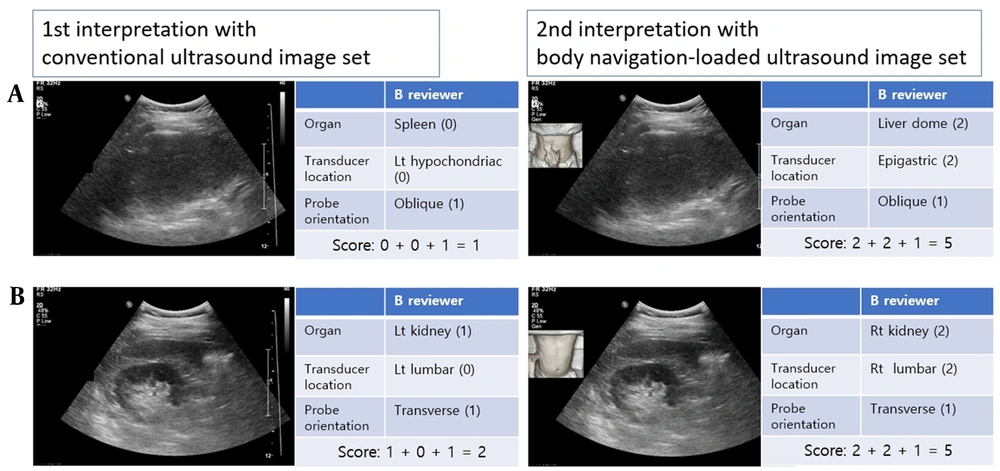
For scoring the transducer location, if it matched the ultrasound operator’s opinion, it was assigned a score of two. If it was found to be immediately adjacent in nine abdominal regions (7), it was assigned a score of one. Additionally, a score of one was assigned to the transducer orientation if it matched the operator’s response. Since the transducer angle could change freely during the examination, an angle variation of approximately 10° was defined as a transverse or longitudinal transducer orientation. Figure 3 presents a scoring example.
Ultrasound image interpretation and scoring. A, This case is evaluated in an oblique scan of the left hypochondriac region by identifying the spleen in the ultrasound image in the first interpretation. However, in the second interpretation, it was confirmed that the transducer is located in an epigastric region; therefore, reviewer B could accurately identify that the liver dome was captured by the ultrasound image. B, In the first interpretation of reviewer B, a transverse scan of the kidney was perceived; however, the left and right sides could not be distinguished; therefore, the score of the first interpretation was two. However, the second interpretation using body navigation-loaded ultrasound images shows that it is a transverse scan of the right kidney.
3.6. Statistical Analysis
The mean differences between the assessments were evaluated using Wilcoxon signed-rank test in SPSS version 20.0 for Windows (IBM Corp. Released 2011. IBM SPSS Statistics for Windows, Version 20.0. Armonk, NY: IBM Corp.). The inter-rater agreement of the three reviewers was determined by measuring the Fleiss’ kappa in SAS version 9.4 (SAS Institute Inc., Cary, NC, USA). The level of statistical significance was set at P < 0.05.
4. Results
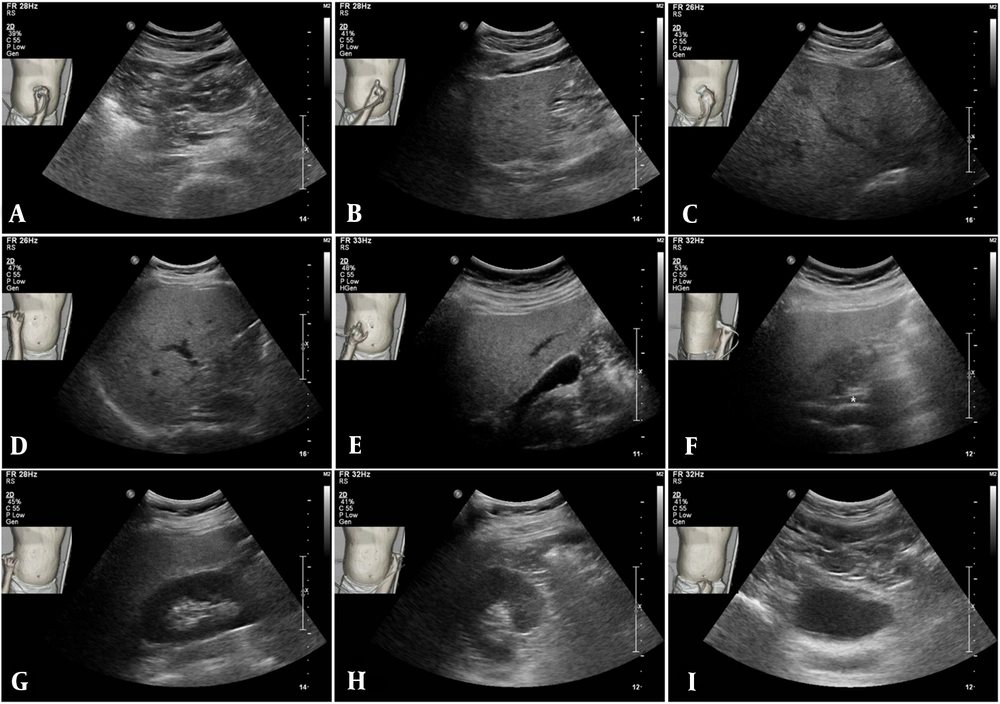
A total of 22 men and seven women were recruited in this study (mean age, 45.1 years; range, 27 - 59 years). The images of various abdominal organs were acquired, along with standard images of the liver, pancreas, kidneys, and urinary bladder (Figure 4).
Application of body navigation-loaded ultrasound in the abdominal imaging of one of the participants. The A, Pancreatic body; B-D, Several hepatic regions; E, Gallbladder; F, Extrahepatic bile duct; G, Right kidney; H, Left kidney, and I, Urinary bladder are shown in order. In addition to the imaged organs, there is information on the inspection site, transducer location, and transducer orientation. The final ultrasound in the middle row is an image of the extrahepatic bile duct (F, asterisk), indicating its acquisition in the left lateral decubitus position.
The selected ultrasound images (n = 203) were classified according to the organs: liver (including portal and hepatic veins, n = 59), extrahepatic bile ducts (n = 12), gallbladder (n = 5), pancreas (n = 19), spleen (n = 15), kidneys (n = 43), urinary bladder (n = 16), bowel (n = 6), psoas muscle (n = 20), aorta (n = 5), uterus (n = 2), and vertebra (n = 1).
The interpretation score of reviewer A was 4.10 ± 1.50 in the first analysis using the conventional ultrasound image set and 4.76 ± 0.63 in the second analysis using the body navigation-loaded ultrasound image set. The corresponding scores of reviewer B in the first and second analyses were 3.82 ± 1.53 and 4.40 ± 0.90, respectively. Also, the corresponding scores of reviewer C were 3.43 ± 1.60 and 4.19 ± 1.01, respectively. There was a significant increase in the interpretation scores of all reviewers (P < 0.001) (Table 1).
| Mean ± SD | Median (IQR) | P-value | |
|---|---|---|---|
| Reviewer A | < 0.001 | ||
| First analysis | 4.10 ± 1.50 | 5 (4 - 5) | |
| Second analysis | 4.76 ± 0.63 | 5 (5 - 5) | |
| Reviewer B | < 0.001 | ||
| First analysis | 3.82 ± 1.53 | 5 (3 - 5) | |
| Second analysis | 4.40 ± 0.90 | 5 (4 - 5) | |
| Reviewer C | < 0.001 | ||
| First analysis | 3.43 ± 1.60 | 4 (2 - 5) | |
| Second analysis | 4.19 ± 1.01 | 5 (3 - 5) |
Abbreviations: SD, standard deviation; IQR, interquartile range.
For all three reviewers, the mean score differences were significant in all analyses, using both the conventional ultrasound image set and the body navigation-loaded ultrasound image set (Table 2).
In the first analysis, the inter-rater agreement regarding the target organ recognition was moderate (Fleiss’ kappa, 0.610), and the estimation of the transducer location and orientation showed a weak agreement (Fleiss’ kappa, 0.425 and 0.571, respectively). In the second analysis, the kappa value increased in all examinations and showed a moderate agreement (Fleiss’ kappa, 0.619 to 0.792). In the first and second analyses, agreement regarding the transducer location was the lowest (Table 3).
| First analysis | P-value | Second analysis | P-value | |
|---|---|---|---|---|
| Reviewer A vs. reviewer B | 4.10 ± 1.50 vs. 3.82 ± 1.53 | 0.006 | 4.76 ± 0.63 vs. 4.40 ± 0.90 | < 0.001 |
| Reviewer B vs. reviewer C | 3.82 ± 1.53 vs. 3.43 ± 1.60 | 0.002 | 4.40 ± 0.90 vs. 4.19 ± 1.01 | < 0.001 |
| Reviewer A vs. reviewer C | 4.10 ± 1.50 vs. 3.43 ± 1.60 | < 0.001 | 4.76 ± 0.63 vs. 4.19 ± 1.01 | < 0.001 |
a Data are presented as mean ± standard deviation.
| Rating category | First analysis | Second analysis | ||
|---|---|---|---|---|
| Fleiss' kappa value (95% CI) | P-value | Fleiss' kappa value (95% CI) | P-value | |
| Target organ recognition (n = 203) | 0.610 (0.551 - 0.669) | < 0.001 | 0.792 (0.743 - 0.841) | < 0.001 |
| Transducer location (n = 203) | 0.425 (0.364 - 0.485) | < 0.001 | 0.619 (0.552 - 0.685) | < 0.001 |
| Transducer orientation (n = 203) | 0.571 (0.500 - 0.642) | < 0.001 | 0.760 (0.702 - 0.819) | < 0.001 |
Abbreviation: CI, confidence interval.
a The Fleiss’ Kappa value is interpreted as follows: 0 - 0.20, none; 0.21 - 0.39, minimal; 0.40 - 0.59, weak; 0.60 - 0.79, moderate; 0.80 - 0.90, strong; and > 0.90, almost perfect.
5. Discussion
In this pilot study, we acquired body navigation-loaded ultrasound images, which included information regarding the inspection site and transducer location. The most important advantage of navigation-loaded ultrasonography is that it increases the operator’s convenience and is expected to allow the operator to focus solely on the ultrasound examination. In some cases, the operator’s increased effort may be required for adding appropriate body marks or text available on the ultrasound equipment to the ultrasound images. This process is both cumbersome and time-consuming, as radiologists or clinicians need to make a diagnosis by acquiring ultrasound images and add a body mark to the image using various control buttons. However, our navigation-loaded images can make this process unnecessary, because the exact information regarding the transducer location and inspection site is automatically integrated in the ultrasound image in real time. Therefore, the navigation-loaded ultrasound image is expected to assist in interpreting ultrasound images when distinction between the right and left sides is important, or when it is necessary to mark specific locations (e.g., ultrasound-guided procedures). The disadvantage of our semi-automated technology compared to the existing ultrasound body mark system is that it takes a few minutes to fix the camera and set the software right before the ultrasound examination.
In the analysis of ultrasound images, the mean interpretation scores of all raters increased significantly by using the body navigation-loaded ultrasound images compared to conventional ultrasound images. It was also confirmed that the inter-rater agreement improved in the second analysis using the navigation-loaded ultrasound image set. Therefore, body navigation-loaded ultrasound imaging allows physicians to interpret ultrasound images more accurately and objectively. Nevertheless, based on the present results, the presence or absence of navigation-loaded images did not significantly influence the target organ identification of easily recognizable organs, such as the left lateral section of the liver, portal vein bifurcation, spleen, or urinary bladder; these organs were identified in nearly 100% of cases in all primary and secondary analyses.
In the present study, there was a significant difference in the interpretation scores of the reviewers (Table 2). Reviewer A (a senior radiologist) had a higher interpretation score than others. Apart from the low scores of the less experienced resident, the observed difference in the scores of the two experienced radiologists, interpreting the navigation-loaded ultrasound images in the second analysis, was related to the transducer location interpretation.
Considering the evaluation of the boundaries of nine abdominal regions, the senior radiologist’s interpretation of the transducer location was more consistent with the operator's intention. Since it was possible to have a subjective interpretation of the boundary area, the inter-rater agreement for the transducer location was lower than that of other evaluation categories (Table 3). By using the four abdominal quadrants with a clear anatomical landmark of the umbilicus as the standard for interpreting the transducer location, all raters were expected to have a higher interpretation score and a high level of agreement.
There are several limitations to this pilot study on this experimental technology. First, the economic or diagnostic efficacy of this technology compared to the conventional ultrasound body mark system was not evaluated. Some physicians may assume that this technology has no significant advantage over the current graphic body mark systems. Although this pilot study was only conducted on abdominal ultrasounds, where the standard view protocol is commonly applied, it can be also useful for examining other organs, such as the musculoskeletal joints, peripheral vascular system, and breasts, where information on the inspection site and transducer is more important than the abdomen. Second, there was a trade-off between protection of patient privacy and increasing the accuracy of the inspection site and transducer information. In this study, navigation-loaded images were acquired with a low-resolution thumbnail, focusing on the protection of patient privacy. Besides, this technology uses artificial intelligence to automatically crop sensitive areas, remove the patients’ faces (8-10), or completely replace them with a simple body mark according to the inspection site and maintain the appropriate field of view. Nevertheless, considering the patient privacy issues, it is expected to be of limited use in gynecological transvaginal or translabial ultrasounds. To resolve this issue, the camera function in the software should be disabled, followed by a conventional ultrasound examination. This method can be easily applied even if the patient refuses a new body marking system. Third, because camera installation and special software settings are required before starting the ultrasound, this process can be quite cumbersome. To overcome this shortcoming, we plan to develop an embedded system that employs the aforementioned artificial intelligence technology. Fourth, our system is expected to be inaccurate for cine-loop images, as it only provides information on the static ultrasound transducer. However, in the future, we will be able to determine the probe movements via software improvements if necessary. Fifth, although the inter-rater agreement increased using the body navigation-loaded images, the Fleiss’ kappa value did not increase above 0.80 (Table 3). Therefore, it cannot completely replace the existing annotation methods, such as text or arrows.
In conclusion, according to the results of this pilot study, the body navigation-loaded ultrasound technology is expected to assist with a simple and objective interpretation of ultrasound images of body organs; it is also expected to improve the operator’s convenience by reducing the use of body marks or text mark systems. Moreover, the application of this technology is anticipated for various body organs through further technological advances.
