1. Background
Breast cancer is the most common type of cancer in women. It can often be treated if it is detected in time. Mammography is a good standard in the diagnosis of breast cancer. X-ray radiation is an ionizing radiation that can increase the risk of cancer in patients (1). Since glandular tissue (acinar, ductal epithelium, and associated stroma) is a radiosensitive organ (2), breast dosimetry is considered to be an important method for studying the risk of glandular tissue harm from mammography examination (3). The average dose absorbed in the central region of the breast, i.e. glandular tissue, is called mean glandular dose (MGD). International commission on radiological protection (ICRP) suggests that MGD within the breast is the best used quantity to indicate the radiation risk, which is used in the European protocol (1). Indeed, MGD is the energy deposited per unit mass of glandular tissue averaged over all the glandular tissue in the breast (3). The breast tissues are assumed to be homogeneous tissues in the assessment of MGD. The energy absorbed in the adipose tissue and skin is not included in the calculation of MGD because the carcinogenic risk in them is considered to be minimal (3).
According to the ALARA principle, the total absorbed dose in the glandular tissue should be kept as low as possible (4). Also, the international atomic energy agency (IAEA) recommends that the MGD value must be less than 3.0 mGy for 42 mm of compressed breast consisting of 50% glandular and 50% adipose tissues (5).
We assumed that the condition of electron equilibrium is satisfied in the breast tissue because the energy of photonic spectrum is low. Therefore, it is true to assume that the absorbed dose is the same and equal to kerma (4). The factors that affect MGD calculations are radiation transport simulation code, cross section data, X-ray spectra, half value layer (HVL), mAs, skin and adipose layer thicknesses, tissue composition, breast shape and size, thickness of breast support, backscattering materials, and presence and absence of a compression plate (3). In the past decades, molybdenum/molybdenum (Mo/Mo) anode/filter combination was generally used in conventional mammography (6).
2. Objectives
In this study, we assessed MGD for W/Ag, W/Rh and Rh/Al anode/filters that were used in modern mammography systems. In mammography, the dose is high for women who have large breasts, and a shift to harder X-ray spectra is effective; that is why tungsten anode is under new investigations (2). A study conducted by Dance et al. showed that if W/Rh combination was used instead of Mo/Mo, the mean glandular dose to the breast tissue could be reduced up to 50% (7). This study also conveyed that the dose of Mo/Mo anode/filter was high only for breast thickness of 2 cm. For all other thicknesses and glandularities, each of the alternative anode/filter combinations Mo/Rh, W/Rh, Rh/Rh and Rh/Al had a lower dose for the same contrast-to-noise ratio (CNR). Then they suggested that for thicknesses of 4 cm to 6 cm, W/Rh was preferred (7). Dance et al. calculated MGD with Monte Carlo simulation and their work is the basis of calculating MGD in breast dosimetry protocols (8). The Monte Carlo technique is an alternative method for a precise simulation of radiation transport in a breast model and is an accurate determination of the mean glandular dose absorbed in the breast (3).
For detection of micro calcifications and tumors, Bernhardt et al. calculated MGD for different breast thicknesses and compositions, anode/filter combinations, different filter thicknesses, and different tube voltages. They have shown that for all breast thicknesses and compositions, the W/Rh target/filter combination is the best choice in digital mammography (9). Baldelli et al. said that by using a W/Rh target/filter, they achieved the same CNR with a lower dose than using Mo/Mo or Mo/Rh. They showed that the result is valid for all breast thicknesses, but it is more significant for the breasts with high thicknesses (6).
3. Materials and Methods
We studied factors that have effects on calculating MGD during mammography examinations with X-ray radiation in the glandular tissue of the breast. We used MCNPX Monte Carlo simulation code.
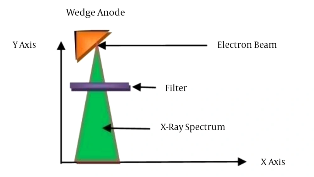
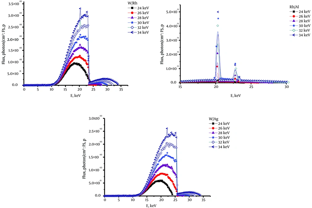
In mammography, low energy X-ray is used for breast imaging. In this study, the MCNPX code, version2.6.0 (10) was used for photon transport simulation to calculate the X-ray spectra and to estimate MGDs. We calculated MGDs in 2 steps. First, we simulated X-ray tube of full field digital mammography system “Midi-Future” (Brestige, Korea) with simple geometry and achieved X-ray spectra of different anode/filters like W/Rh, W/Ag, Rh/Al in the tube voltage range of 24 to 32 kV with 2 kV intervals. According to the simple configuration displayed in Figure 1, mono energetic electrons collide to the anode and X-ray spectra will be produced. The spectra for Rh, Ag and Al filters with thicknesses of 50 μm, 75 μm and 1 mm, respectively, are shown in Figure 2.
In the second step of simulation, the obtained X-ray spectra were set as a source in the input file for calculating MGDs. We considered a compressed breast phantom between two plates in the mammography system, i.e. compression pedal and support plate of the breast. The X-ray source was 64 cm above the top surface of the breast phantom.
3.1. The Phantom
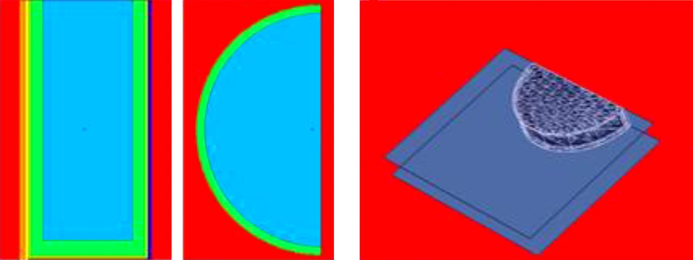
The compressed breast phantom in the cranio-caudal projection was a semicircular cylinder with 8.6 cm of radius and between 3 and 8 cm of thickness. According to Figure 3, it includes three nested semi-cylinder skin, adipose and glandular tissues. Glandular-adipose region in the central part of the breast phantom was a semi-cylinder with 8 cm radius, surrounded by 0.5 cm of adipose tissue layer. A skin layer with a thickness of 1 mm was surrounding the adipose tissue. Elemental compositions and densities of the glandular and adipose tissues were used according to Hammerstein et al. data (11) and international commission on radiation units and measurements (ICRU) Report No. 44 (12).
The mass energy absorption coefficients of gland and adipose tissue in different energies that were used in the calculation of MGD were taken from the National institute of standards and technology (NIST) database and XCOM photon cross section compilations (13, 14).
The support plate material is a carbon fiber with 1.45 g/cm3 density and 1 mm thickness and compression pedal material is a polycarbonate with 1.2 g/cm3 density and 1.2 mm thickness (5). Using F6: P tally (energy deposition averaged over a specific volume as a geometry cell) in MCNPX code, we investigated the absorbed energy in unit mass of breast tissue, MeV/g. As mentioned before, the breast tissue was considered as a homogeneous mixture of gland and adipose tissues. Therefore, for each glandular g (0% to 100%), we calculated the weight fraction of all the elements in the breast tissue with the help of a Fortran Power Station (version 4) program and data of Hammerstein et al. (11).
3.2. Mean Glandular Dose
Using the following Equations (Equations 1-3) we can calculate the mean glandular dose. The density of the breast tissue based on glandular g is given by:

Where ρa and ρg are the densities of adipose and glandular tissues, respectively (ρa = 1.04 g/cm3 and ρg = 0.93 g/cm3) and the glandular g is the ratio of the glandular tissue to the breast tissue and 1-g is the ratio of the adipose tissue to the breast tissue by weight (12). The portion of the absorbed energy in the glandular tissue of the breast, G, due to the glandular g is:

Where (µen/ρ)g and (µen/ρ)a are the photon mass absorption coefficients of the glandular and the adipose tissues, respectively (15).
MGD can be obtained from the absorbed dose distribution D(E) as the output of F6 tally in energy bins in the breast tissue:

The integral of D(E) is the mean glandular dose (MGD) to the breast tissue (1). To compare with other works, the MGD values are expressed in units of mGy.
3.3. MCNP Code
MCNP is a general purpose Monte Carlo code that can be used for neutron, photon and electron or coupled neutron/photon/electron transport in a large range of energy. In this study, we used version MCNPX 2.6.0. In MCNP code, three-dimensional coordinates are used to define geometric cell, surface and interaction environment. MCNPX 2.6.0 is the next generation in the series of Monte Carlo transport codes that began at Los Alamos National Laboratory in 2008 after the development of MCNPX2.5.0 and MCNP4C. Improvement of physics simulation models, extension of neutron, proton, and photonuclear libraries to 150 MeV and formulation of new variance-reduction and data-analysis techniques are the most considerable characteristics of this code (10).
3.4. XCOM Database
XCOM web program database can be used to calculate total attenuation coefficients, for any element, compound or mixture (Z ≤ 100), as well as photon cross sections for incoherent scattering, coherent scattering, photoelectric absorption and pair production at energies from 1 keV to 100 GeV. Tables in XCOM program include cross sections for many elements. Photon cross sections for compounds or mixtures can be obtained accurately as a weighted summation of the cross sections for the atomic constituents except for energies close to absorption edges.
The sum of the interaction coefficients for the individual processes is equal to the total attenuation coefficient. The weighting factors, which are the fractions by weight of the components in the compounds, are calculated by XCOM from the chemical formula that the user entered (14).
4. Results
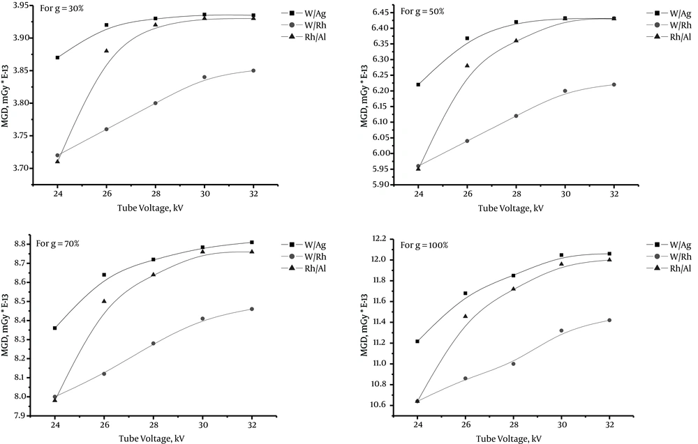
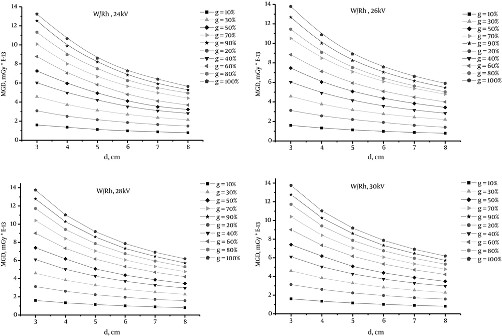
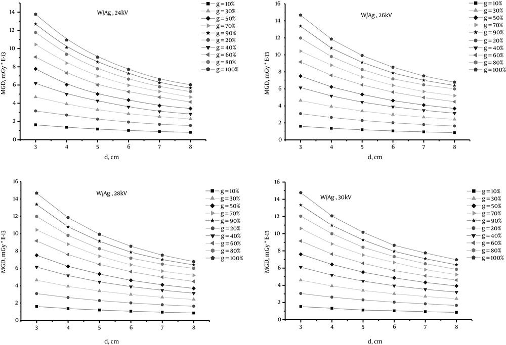
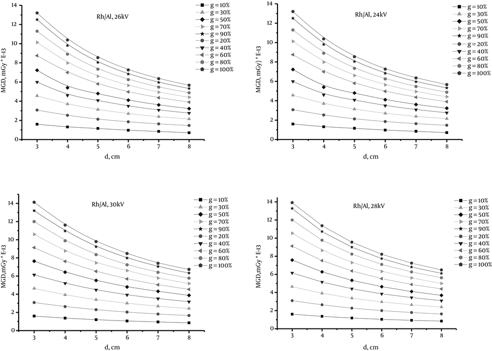
In this investigation, we calculated MGDs for W/Rh, W/Ag and Rh/Al anode-filter combinations using MCNPX2.6.0 code and studied the effects of varying breast phantom thickness, glandularity and different X-ray tube voltages on MGD value. In all simulating results, statistical error was less than 3%. In Tables 1-3, calculated MGD values for 3 different anode/ filters are presented. In Figures 4 - 6, for each anode-filter combinations, we plotted MGD versus breast thickness for all the g values from 10% to 100% and tube voltages between 24 to 32 kV. In Figure 7, we compared our results with the findings of Boone et al. (16) for MGD versus breast thickness for W/Rh and W/Ag at 100% glandularity. In Figure 8, for breast phantom with 4 cm thickness and 30%, 50%, 70% and 100% glandularity, the MGD was plotted against the tube voltage of 24 kV to 32 kV for W/Ag, W/Rh and Rh/Al target/filter combination.
| g | |||||||||||
|---|---|---|---|---|---|---|---|---|---|---|---|
| d, cm | 0% | 10% | 20% | 30% | 40% | 50% | 60% | 70% | 80% | 90% | 100% |
| For W-Rh at 24 kV | |||||||||||
| 3 | 0 | 1.58 | 3.05 | 4.57 | 6.03 | 7.26 | 8.78 | 10.08 | 11.33 | 12.53 | 13.23 |
| 4 | 0 | 1.36 | 2.49 | 3.72 | 4.94 | 5.96 | 7.03 | 8.0 | 8.98 | 9.88 | 10.63 |
| 5 | 0 | 1.12 | 2.14 | 3.13 | 4.20 | 4.93 | 5.82 | 6.66 | 7.5 | 8.2 | 8.6 |
| 6 | 0 | 0.975 | 1.85 | 2.7 | 3.52 | 4.11 | 4.79 | 5.65 | 6.25 | 6.83 | 7.26 |
| 7 | 0 | 0.87 | 1.64 | 2.36 | 3.08 | 3.5 | 4.11 | 4.96 | 5.47 | 5.92 | 6.4 |
| 8 | 0 | 0.77 | 1.48 | 2.14 | 2.82 | 3.23 | 3.69 | 4.41 | 4.95 | 5.29 | 5.64 |
| For W-Rh at 26 kV | |||||||||||
| 3 | 0 | 1.60 | 3.08 | 4.58 | 6.04 | 7.47 | 8.84 | 10.21 | 11.45 | 12.68 | 13.78 |
| 4 | 0 | 1.37 | 2.57 | 3.76 | 4.95 | 6.04 | 7.12 | 8.11 | 9.08 | 10.01 | 10.86 |
| 5 | 0 | 1.13 | 2.19 | 3.18 | 4.21 | 5.07 | 5.93 | 6.68 | 7.52 | 8.24 | 8.91 |
| 6 | 0 | 0.98 | 1.9 | 2.76 | 3.58 | 4.36 | 5.08 | 5.75 | 6.41 | 7.04 | 7.58 |
| 7 | 0 | 0.88 | 1.65 | 2.44 | 3.16 | 3.84 | 4.48 | 5.07 | 5.63 | 6.14 | 6.62 |
| 8 | 0 | 0.78 | 1.49 | 2.19 | 2.84 | 3.42 | 4.00 | 4.5 | 5.04 | 5.48 | 5.90 |
| For W-Rh at 28 kV | |||||||||||
| 3 | 0 | 1.61 | 3.10 | 4.60 | 6.09 | 7.52 | 8.96 | 10.3 | 11.61 | 12.76 | 13.85 |
| 4 | 0 | 1.4 | 2.58 | 3.79 | 5.008 | 6.10 | 7.23 | 8.28 | 9.26 | 10.12 | 10.95 |
| 5 | 0 | 1.14 | 2.20 | 3.23 | 4.22 | 5.10 | 6.06 | 7.06 | 7.68 | 8.32 | 9.07 |
| 6 | 0 | 0.99 | 1.92 | 2.80 | 3.66 | 4.40 | 5.21 | 6.10 | 6.59 | 7.15 | 7.79 |
| 7 | 0 | 0.89 | 1.7 | 2.48 | 3.23 | 3.90 | 4.59 | 5.35 | 5.77 | 6.34 | 6.75 |
| 8 | 0 | 0.79 | 1.53 | 2.24 | 2.91 | 3.43 | 4.11 | 4.65 | 5.16 | 5.58 | 6.03 |
| For W-Rh at 30 kV | |||||||||||
| 3 | 0 | 1.62 | 3.15 | 4.61 | 6.11 | 7.55 | 9.00 | 10.4 | 11.72 | 12.77 | 13.86 |
| 4 | 0 | 1.35 | 2.62 | 3.84 | 5.04 | 6.19 | 7.34 | 8.40 | 9.42 | 10.27 | 11.32 |
| 5 | 0 | 1.16 | 2.24 | 3.28 | 4.28 | 5. 11 | 6.17 | 7.07 | 7.87 | 8.6 | 9.179 |
| 6 | 0 | 1.016 | 1.94 | 2.84 | 3.72 | 4.42 | 5.33 | 6.11 | 6.76 | 7.33 | 7.87 |
| 7 | 0 | 0.905 | 1.72 | 2.52 | 3.29 | 3.91 | 4.71 | 5.36 | 5.94 | 6.46 | 6.91 |
| 8 | 0 | 0.817 | 1.58 | 2.28 | 2.97 | 3.48 | 4.22 | 4.78 | 5.32 | 5.72 | 6.19 |
| For W-Rh at 32 kV | |||||||||||
| 3 | 0 | 1.66 | 3.16 | 4.62 | 6.33 | 7.56 | 9.00 | 10.4 | 11.74 | 12.98 | 14.28 |
| 4 | 0 | 1.36 | 2.63 | 3.845 | 5.05 | 6.20 | 7.37 | 8.45 | 9.45 | 10.5 | 11.41 |
| 5 | 0 | 1.17 | 2.25 | 3.29 | 4.31 | 5.28 | 6.22 | 7.08 | 7.9 | 8.7 | 9.44 |
| 6 | 0 | 1.020 | 1.95 | 2.88 | 3.76 | 4.59 | 5.39 | 6.14 | 6.84 | 7.5 | 8.12 |
| 7 | 0 | 0.91 | 1.76 | 2.56 | 3.32 | 4.06 | 4.8 | 5.42 | 6.03 | 6.59 | 7.16 |
| 8 | 0 | 0.82 | 1.59 | 2.30 | 3.008 | 3.69 | 4.28 | 4.86 | 5.4 | 5.93 | 6.38 |
aAll numbers should be multiplied by E-13, Tungsten/Rhodium (W/Rh).
| g | |||||||||||
|---|---|---|---|---|---|---|---|---|---|---|---|
| d, cm | 0% | 10% | 20% | 30% | 40% | 50% | 60% | 70% | 80% | 90% | 100% |
| For W-Ag at 24 kV | |||||||||||
| 3 | 0 | 1.5 | 3.05 | 4.64 | 6.05 | 7.40 | 9.07 | 10.39 | 11.76 | 12.68 | 13.76 |
| 4 | 0 | 1.41 | 2.55 | 3.87 | 5 | 6.22 | 7.32 | 8.36 | 9.37 | 10.1 | 11.2 |
| 5 | 0 | 1.14 | 2.25 | 3.28 | 4.27 | 5.01 | 6.01 | 6.97 | 7.78 | 8.51 | 9.05 |
| 6 | 0 | 1.01 | 1.93 | 2.84 | 3.6 | 4.35 | 5.26 | 5.96 | 6.64 | 7.26 | 7.71 |
| 7 | 0 | 0.89 | 1.68 | 2.52 | 3.1 | 3.74 | 4.66 | 5.28 | 5.81 | 6.23 | 6.61 |
| 8 | 0 | 0.80 | 1.55 | 2.27 | 2.82 | 3.42 | 4.14 | 4.68 | 5.28 | 5.66 | 6.03 |
| For W-Ag at 26 kV | |||||||||||
| 3 | 0 | 1.55 | 3.08 | 4.67 | 6.07 | 7.5 | 9.13 | 10.4 | 11.93 | 13.28 | 14.57 |
| 4 | 0 | 1.35 | 2.6 | 3.915 | 5.168 | 6.36 | 7.52 | 8.64 | 9.7 | 10.72 | 11.7 |
| 5 | 0 | 1.15 | 2.28 | 3.36 | 4.41 | 5.35 | 6.36 | 7.28 | 8.14 | 8.96 | 9.73 |
| 6 | 0 | 1.04 | 2.01 | 2.94 | 3.85 | 4.6 | 5.52 | 6.28 | 7.008 | 7.7 | 8.35 |
| 7 | 0 | 0.93 | 1.79 | 2.6 | 3.42 | 4.16 | 4.88 | 5.55 | 6.13 | 6.77 | 7.4 |
| 8 | 0 | 0.84 | 1.61 | 2.368 | 3.088 | 3.7 | 4.38 | 4.99 | 5.55 | 6.06 | 6.56 |
| For W-Ag at 28 kV | |||||||||||
| 3 | 0 | 1.56 | 3.10 | 4.67 | 6.13 | 7.51 | 9.14 | 10.45 | 11.98 | 13.38 | 14.67 |
| 4 | 0 | 1.36 | 2.64 | 3.92 | 5.17 | 6.4 | 7.59 | 8.72 | 9.80 | 10.78 | 11.8 |
| 5 | 0 | 1.16 | 2.3 | 3.39 | 4.44 | 5.34 | 6.46 | 7.39 | 8.27 | 9.12 | 9.92 |
| 6 | 0 | 1.045 | 2.015 | 2.98 | 3.89 | 4.68 | 5.62 | 6.41 | 7.17 | 7.86 | 8.54 |
| 7 | 0 | 0.94 | 1.80 | 2.66 | 3.47 | 4.17 | 4.98 | 5.68 | 6.48 | 7.01 | 7.52 |
| 8 | 0 | 0.85 | 1.63 | 2.41 | 3.14 | 3.8 | 4.49 | 5.20 | 5.8 | 6.38 | 6.78 |
| For W-Ag at 30 kV | |||||||||||
| 3 | 0 | 1.58 | 3.12 | 4.77 | 6.14 | 7.64 | 9.15 | 10.57 | 12 | 13.39 | 14.75 |
| 4 | 0 | 1.371 | 2.65 | 3.93 | 5.18 | 6.42 | 7.64 | 8.75 | 9.92 | 10.98 | 12.048 |
| 5 | 0 | 1.18 | 2.33 | 3.40 | 4.45 | 5.56 | 6.53 | 7.52 | 8.4 | 9.28 | 10.128 |
| 6 | 0 | 1.05 | 2.05 | 3.008 | 3.95 | 4.84 | 5.79 | 6.53 | 7.3 | 8.03 | 8.70 |
| 7 | 0 | 0.95 | 1.85 | 2.704 | 3.53 | 4.3 | 5.08 | 5.8 | 6.46 | 7.08 | 7.73 |
| 8 | 0 | 0.867 | 1.68 | 2.44 | 3.2 | 3.9 | 4.57 | 5.22 | 5.82 | 6.39 | 6.93 |
| For W-Ag at 32 kV | |||||||||||
| 3cm | 0 | 1.59 | 3.2 | 4.80 | 6.15 | 7.65 | 9.16 | 10.6 | 12.03 | 13.4 | 14.79 |
| 4cm | 0 | 1.38 | 2.68 | 3.91 | 5.2 | 6.43 | 7.65 | 8.81 | 10.01 | 10.99 | 12.06 |
| 5cm | 0 | 1.2 | 2.35 | 3.4 | 4.5 | 5.58 | 6.56 | 7.55 | 8.42 | 9.30 | 10.16 |
| 6cm | 0 | 1.06 | 2.08 | 3.008 | 3.95 | 4.86 | 5.79 | 6.56 | 7.34 | 7.94 | 8.75 |
| 7cm | 0 | 0.96 | 1.86 | 2.75 | 3.54 | 4.34 | 5.10 | 5.82 | 6.51 | 7.09 | 7.76 |
| 8cm | 0 | 0.87 | 1.69 | 2.45 | 3.21 | 4.01 | 4.60 | 5.24 | 5.85 | 6.4 | 6.97 |
aAll numbers should MGD: be multiplied by E-13.
| g | |||||||||||
|---|---|---|---|---|---|---|---|---|---|---|---|
| d, cm | 0% | 10% | 20% | 30% | 40% | 50% | 60% | 70% | 80% | 90% | 100% |
| For Rh-Al at 24 kV | |||||||||||
| 3 | 0 | 1.59 | 3.07 | 4.56 | 6 | 7.23 | 8.75 | 10.13 | 11.3 | 12.51 | 13.2 |
| 4 | 0 | 1.32 | 2.53 | 3.71 | 4.9 | 5.95 | 6.99 | 7.98 | 8.91 | 9.8 | 10.64 |
| 5 | 0 | 1.16 | 2.12 | 3.13 | 4.08 | 4.8 | 5.8 | 6.6 | 7.34 | 8.04 | 8.54 |
| 6 | 0 | 0.97 | 1.85 | 2.7 | 3.5 | 4.11 | 4.97 | 5.64 | 6.25 | 6.83 | 7.26 |
| 7 | 0 | 0.85 | 1.63 | 2.38 | 3.08 | 3.61 | 4.36 | 4.94 | 5.47 | 5.96 | 6.35 |
| 8 | 0 | 0.71 | 1.47 | 2.14 | 2.76 | 3.23 | 3.9 | 4.41 | 4.88 | 5.32 | 5.66 |
| For Rh-Al at 26 kV | |||||||||||
| 3 | 0 | 1.60 | 3.08 | 4.57 | 6.04 | 7.31 | 8.84 | 10.17 | 11.45 | 12.68 | 13.39 |
| 4 | 0 | 1.33 | 2.56 | 3.87 | 5 | 6.27 | 7.12 | 8.45 | 9.08 | 10.01 | 10.81 |
| 5 | 0 | 1.13 | 2.17 | 3.20 | 4.16 | 4.91 | 5.93 | 6.75 | 7.52 | 8.24 | 8.76 |
| 6 | 0 | 0.98 | 1.88 | 2.76 | 3.58 | 4.20 | 5.08 | 5.77 | 6.41 | 7.02 | 7.45 |
| 7 | 0 | 0.87 | 1.66 | 2.44 | 3.16 | 3.69 | 4.48 | 5.07 | 5.61 | 6.14 | 6.52 |
| 8 | 0 | 0.78 | 1.51 | 2.19 | 2.84 | 3.31 | 4 | 4.54 | 5.02 | 5.48 | 5.82 |
| For Rh-Al at 28 kV | |||||||||||
| 3 | 0 | 1.61 | 3.09 | 4.64 | 6.12 | 7.58 | 9.12 | 10.54 | 12 | 13.0 | 13.92 |
| 4 | 0 | 1.371 | 2.64 | 3.92 | 5.14 | 6.36 | 7.52 | 8.64 | 9.77 | 10.7 | 11.65 |
| 5 | 0 | 1.187 | 2.27 | 3.37 | 4.41 | 5.34 | 6.38 | 7.29 | 8.24 | 9.008 | 9.55 |
| 6 | 0 | 1.046 | 2.01 | 2.96 | 3.85 | 4.64 | 5.53 | 6.32 | 7.1 | 7.74 | 8.22 |
| 7 | 0 | 0.936 | 1.79 | 2.64 | 3.44 | 4.11 | 4.89 | 5.60 | 6.27 | 6.81 | 7.24 |
| 8 | 0 | 0.848 | 1.63 | 2.4 | 3.1 | 3.69 | 4.40 | 5.008 | 5.63 | 6.11 | 6.49 |
| For Rh-Al at 30 kV | |||||||||||
| 3 | 0 | 1.62 | 3.10 | 4.65 | 6.13 | 7.64 | 9.13 | 10.57 | 12.01 | 13.0 | 14.0 |
| 4 | 0 | 1.373 | 2.65 | 3.93 | 5.15 | 6.42 | 7.61 | 8.76 | 9.88 | 10.93 | 11.85 |
| 5 | 0 | 1.20 | 2.30 | 3.4 | 4.38 | 5.42 | 6.51 | 7.45 | 8.36 | 9.23 | 9.79 |
| 6 | 0 | 1.06 | 2.03 | 3.008 | 3.93 | 4.8 | 5.68 | 6.55 | 7.24 | 7.98 | 8.48 |
| 7 | 0 | 0.95 | 1.82 | 2.68 | 3.52 | 4.32 | 5.04 | 5.77 | 6.41 | 7.05 | 7.56 |
| 8 | 0 | 0.86 | 1.66 | 2.43 | 3.18 | 3.88 | 4.54 | 5.18 | 5.77 | 6.33 | 6.75 |
| For Rh-Al at 32 kV | |||||||||||
| 3 | 0 | 1.62 | 3.10 | 4.66 | 6.14 | 7.6 | 9.13 | 10.53 | 12.01 | 13.32 | 14.13 |
| 4 | 0 | 1.38 | 2.65 | 3.92 | 5.16 | 6.43 | 7.61 | 8.72 | 9.89 | 10.97 | 11.95 |
| 5 | 0 | 1.21 | 2.31 | 3.41 | 4.44 | 5.45 | 6.52 | 7.48 | 8.40 | 9.28 | 9.85 |
| 6 | 0 | 1.061 | 2.04 | 3.010 | 3.93 | 4.84 | 5.69 | 6.56 | 7.29 | 8.04 | 8.60 |
| 7 | 0 | 0.952 | 1.83 | 2.70 | 3.53 | 4.3 | 4.97 | 5.83 | 6.48 | 7.12 | 7.57 |
| 8 | 0 | 0.870 | 1.67 | 2.44 | 3.20 | 3.9 | 4.57 | 5.33 | 5.95 | 6.4 | 6.81 |
aAll numbers should be multiplied by E-13.
5. Discussion
The reported results in Figures 4 - 6 show that for any breast model and any target/filter combination, more and less the curves have a similar behavior. MGD decreases as the breast thickness increases from 3 to 8 cm for all percentages of glandularity, as well as with increasing glandularity g, MGD increases too. Because glandular tissue of the breast is sensitive to radiation, so this part absorbs X-ray in mammography exposure and we see in figures 4 to 6 that g and MGD have a direct relationship i.e. with increasing g, MGD increases too and vice versa. In addition, with increasing breast thickness, breast volume increases and the portion of absorbed X-ray in the whole breast reduces in a constant value of g. Therefore, MGD has an inverse relationship with breast thickness.
According to Figure 7, in general, our results are consistent with those of Boone et al. for 100% glandular, but our findings for MGD values are higher than the results of Boone et al. (16). Differences between the MGD values derived in our work and the findings of Boone et al. (16) result from different MGD calculation techniques. Because of the exact transport of photons and electrons in MCNPX code, it is a precise code and it can be said that our results are more accurate than those of Boone et al. For W/Ag and W/Rh combination, by increasing phantom thickness, the discrepancy between the two studies increases, so that for 3 cm phantom thickness, the results for two different combinations are nearly equal and for 8 cm thickness, the discrepancy increases.
According to the curves of Figure 8, the MGD values for the combination of W/Rh in 30%, 50%, 70% and 100% glandularity are always at the lowest rate, whereas those values for the combination of W/Ag are always at the highest rate.
As it is well known, HVL depends on kVp, type of anode/filter which is calculated with regard to the thickness and composition of the breast. Since in mammography systems, the filter does not change, HVL is considered via kVp in MGD calculations. We changed the tube voltage in our MCNP calculations. The obtained results from MCNPX code is normalized per one particle of source. Therefore, mAs does not enter in our MGD calculations because calculate dose is done for one X-ray particle. We can multiply the dose by N (photon numbers) to change the normalized MGD to total dose in the breast. MCNPX calculation is independent of X-ray intensity and has the ability to change to other related quantities.
About the limitation of this study, we can say that the individual’s age and race that affect the percentage of fat and glandular tissue in the breast have not been considered. Moreover, for all breast thicknesses above 8 cm and less than 3 cm, all useful voltages in mammography X-ray tubes and percentage of glandular tissues have not been calculated. Also, we considered the skin thickness fixed and the shape of compact breast as fully semi-cylinder, which in fact may not be a complete semi-cylinder.
In addition, only three anode/filter combinations are examined without considering the effect of filter thickness on different mammography systems. Since the absorbed energy within the breast tissue at usual thicknesses of the breast from 3 to 8 cm and glandular percentages of 10 to 100% and different voltages used in mammography had not already been investigated by using MCNPX code, we found it necessary to calculate the value of MGD in a wide range of mammography tube voltages and various glandular percentages and thicknesses of the breast.
In conclusion, the results show that tissue composition, breast size and anode/filter combination do affect MGD values. Our results are consistent with current published works. Moreover, in comparison with other published data, our findings show that among the new anode/filter combinations W/Ag, W/Rh, and Rh/Al, for different compressed breast thicknesses and different breast glandularity ranging, W/Rh anode/filter is the best choice to deliver a lower dose.
In addition, we aim to calculate CNR for these anode/filter combinations and then by considering figure of merit (FOM), we will conclude that which combination will be the best choice for delivering the lowest dose against the highest image contrast in digital mammography systems.
![Comparing MGD between this study and a study conducted by Boone et al. [15] for W/Rh and W/Ag with 100% glandularity and tube voltage 24, 26 and 32 Kv (W/Rh, Tungsten/Rhodium;W/Ag, Tungsten/ Silver) Comparing MGD between this study and a study conducted by Boone et al. [15] for W/Rh and W/Ag with 100% glandularity and tube voltage 24, 26 and 32 Kv (W/Rh, Tungsten/Rhodium;W/Ag, Tungsten/ Silver)](https://services.brieflands.com/cdn/serve/3170b/9317137cbcab5d7a62f426397ecc8fda96c96297/iranjradiol-13-04-36484-i005-preview.webp)
