1. Background
Electron beam is widely used for treatment of non-deep lesions, because of its most important advantage over the photon beam: lesser dose delivery to normal tissues beyond of the tumor, due to its steep dose gradient relative to the depth. This capability leads to employ it in radiation therapy of nasal, breast, and parotid regions (1, 2). On the other side, its usage is limited by the dependency of penumbra to the depth and influence of dose parameters of electron beam from the field size changing (3-8). The issue of penumbra increment by depth is enhanced in some investigations by adding a narrow photon beam to the edge of the electron beam field (5) or mixing a low weight photon to electron beam field (4, 9, 10). To our knowledge, no study on small fields for mixed electron and photon beam has been reported. In additional, none of these studies carried out for producing the simultaneous mixed electron and photon beam, they mixed the beams separately with conventional configuration of the linac machine.
2. Objectives
In this study, improvement of the penumbra and Dmax changes will be investigated. Also, the effects of cut-outs on the beam parameters prepared as well.
3. Materials and Methods
3.1. Measurements
For tuning of the MC code, the PDD and profile curve of 16 MeV electron beam of Varian 2300/CD linac was measured. The profile measurements was obtained at the 1, 3.5, and 7 cm depths. The PTW parallel plane Markus camber type 34045 with 0.02 cm3 sensitive volume was used for percentage depth dose (PDD) and profile measurements of 10 × 10 cm2 applicator in PTW 3D water phantom MP3 at 100 cm source to surface distance (SSD) condition. The air gap between bottom side of applicator and the water phantom surface was 5 cm. The PDD was obtained from percentage depth ionization (PDI) conversion according to the IAEA TRS 398 protocol (11).
3.2. Monte Carlo Simulation
By employing the MCNPX version 2.6 (12) running in a PC with core i5 Intel processor and 4 GB RAM, the simulations has performed.
The primary and secondary scattering foil of Varian 2300/CD linac head was simulated. The primary scattering foil had a 0.5 mm thickness Aluminum foil, and the secondary scattering foil was a Tantalum cone with base radius of 20 mm and 5 mm height (13, 14). The source had 1.15° angular distribution. The collimator jaws were composed of Tungsten and the applicator scrapers made of zinc alloy (15) and the standard cut-out of applicator bottom was of Cerrobend alloy (52.5% Bi, 32% Pb, 15.5% Sn). The simulated water phantom was a 50 × 50 × 50 cm3 of H2O. For the PDD calculation the central axis in water phantom was divided into 0.2 × 0.2 × 0.2 cm3 cubes (voxels). For dose profile calculation the depths of 1, 3.5, and 7 cm were divided to the same voxels. By employing Mesh Tally type 3 the energy deposition in each voxels were calculated. The mesh tally type 3 scores the energy deposition from all particles. The tally values of each voxel constitutes the points of PDD and dose profile curves.
In the next step, for producing the simultaneous mixed electron and photon beam, the Pb sheet (perforated target) with the thickness of 1 and 2 mm punched with 0.2, 0.3, and 0.5 cm diameter holes. The center-to-center distance of these holes were 0.9 cm. These cylindrical holes allows to the electrons to passing through them, and on the other hand, the striking of electrons on the Lead sheet produces the bremsstrahlung photon beam. This layer was placed at 39 cm from the phantom surface, above the applicator holder tray (first scraper of applicator). The reason for choosing the Pb for x-ray production are: its high atomic number (Z = 82), low price and easy molding. According to provided documents by Siemens and Varian linac manufactures, the linac target is made of Gold (Z = 79) or Tungsten (Z = 74).
At the bottom of the Lead layer, at the distance of 37 cm from the phantom surface, the scattering component is placed. This component is used for scattering of the passed electrons from the Lead layer for uniform the electron beam distribution in the radiation field. It is composed of two layers: 1-a wide steel layer which covers the whole of passed electrons through the Pb layer, act as scattering layer for all electrons, 2- a 3 × 3 cm2 steel layer at the top of the first layer for reducing the intensity of central areas of the electron radiation field for flattening of the beam profile. Each of the steel layers had 1 mm thickness. The simulated geometry for producing the mixed beam is illustrated in Figure 1.
a) The exited electron beam from the head of linac collimator incidence on the b) perforated Lead target, c1) The first steel scattering foil for reducing the intensity of center of electron beam, c2) The second scattering foil, d) The Lead shield for blocking the scattered photons and electrons, e) The applicator holder tray.
4. Results
4.1. The Tuning of the Simulation
The measured R50 and RP for 10 × 10 cm2 field were 6.5 and 7.8 cm, respectively, and these values in simulation were 6.6 and 7.9 cm. Therefore the E0 (mean) in measurement and simulation are equal to 15.1 and 15.4 MeV. Other points of the PDD curve were had smaller than 2% difference between measurement and simulation. The penumbra 20% - 80%, the distance between 20% and 80% dose points of profile curve, at the depth of 1 cm for both of measurement and simulation were 1.2 cm, which increased to 5.5 and 5.4 cm for measurement and simulation at the depth of 7 cm. Due to the compliance of measure and simulated PDD and profiles, the mixed beam production components placed at the electron beam path.
4.2. The Simulations With the Mixed Beam Production Layers
By accounting the perforated Lead layer and steel scattering layers in the beam interactions, the mixed beam was produced. The PDD and profile of 10 × 10 cm2 field were calculated for same depths same as the pure electron beam. The PDD of the mixed beam, has a shrink buildup region and a smoother dose fall-off after this part of PDD curve in comparison with the pure electron beam. The photon percentage for 1 mm thickness with 0.2, 0.3, and 0.5 cm holes diameter Lead layer target was about 33%, 32%, and 28% and for 2 mm targets punched with 0.2, 0.3, and 0.5 cm holes, the x-ray percentages were 43%, 41%, and 35%. Also, without the target layer the simulation is repeated and the contaminated photon was 15%, that mostly produced by scattering layers. These percentages were measured at the depth of RP, which is beyond of the practical range of electrons (RP).
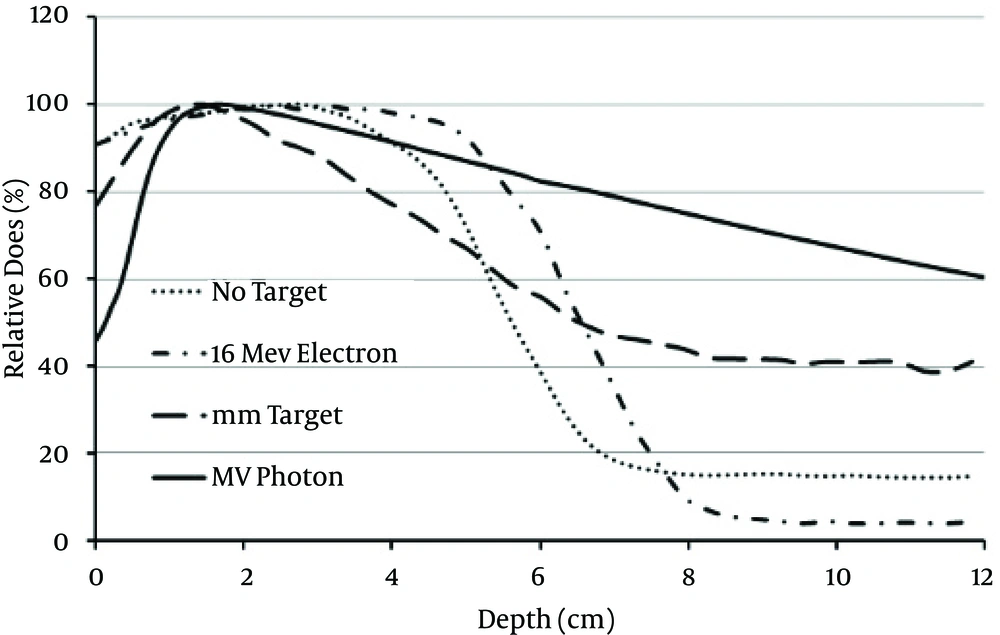
The R100, R50, RP and RP’ are equal to 1.6, 5.5, 6.7 and 8.2 cm for 1 mm target with 0.3 cm holes. Also, the surface dose was reduced to 80% that was 92% for pure 16 MeV electron and 49% for pure 6 MV photon. The PDDs of produced mixed beam by 1 and 2 mm targets illustrated in Figure 2. Also, the different of electron, photon, and mixed beam PDDs is shown in Figure 3.
The penumbra, at the same depths of simulation, didn’t showed a significant different between various targets with same thickness. For example, at the depth of 3.5 cm it was changed from 3.8 to 4.0 cm while the diameters of the target holes changed from 0.2 to 0.5 cm for 1 mm thickness target, and changed from 4.9 to 4.8 cm for 2 mm thickness target. Also, the penumbra in that depth without the target was 4.7 cm.
Figure 4 shows the profile of pure 16 MeV electron and the mixed beams. In this figure the difference of penumbra changing by depth is obvious. The percentage of penumbra changes with the depth is obviously smaller for mixed beam in comparison with the pure electron. The minimum variation of penumbra was observed for 2 mm target with 0.2 cm holes. In general, the 2 mm target had a smaller changes in penumbra with the depth. In comparison with the pure electron, the mixed beam shows a useful specificity for treatment of semi-deep targets, which the dose field size is not suffering from the large changes. In the case of 2 mm target with 0.2 holes the penumbra variation is 21% which it is 31% for pure photon and 350% for pure electron beam.
4.3. Small Field Size (Cut-Outs)
4.3.1. The 4 × 4 cm2 Cut-Out
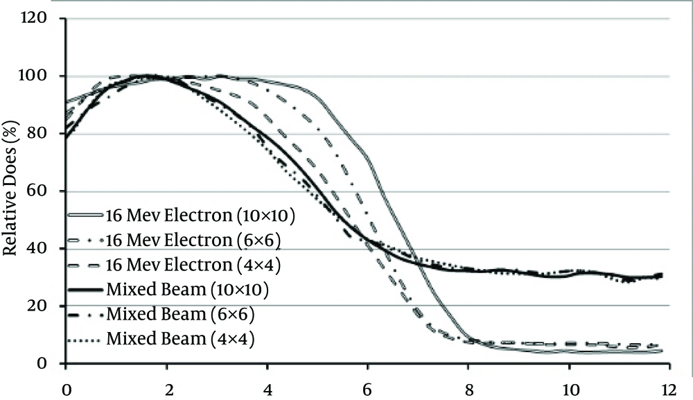
The R50, RP, and Rp’ in the pure electron mode were 6.6, 7.9, and 8.0 cm which by inserting the 4 × 4 cm2 width cut-out they are reduced to 5.7, 7.3, and 7.6 cm. The flatness at the depths of 1 and 7 cm were 101 % to 120 %. Also, the penumbras changes were 80 %.
But for the mixed beam, produced by 1 mm target with 0.3 cm holes, without and with this cut-out the R50 were 5.5 and 5.4 cm and Rp’ were 8.8 and 8.9 cm. The changes of PDD parameters has a slight variation in comparison with the 10 × 10 cm2 field size. Aside from these, the overall shape of the PDDs of mixed beam for cut-out mode and 10 × 10 cm2 field size are very similar. Also, the flatness was 102 ± 1 % for the three depths. The penumbras changes between 1 and 7 cm depths were -40% that shows dose fall-off sharpening for profile at the deeper depths. This is arise from the fact that the effect of wide target and geometrical penumbra is reduced by using the cut-out.
The penumbra and flatness changes were -6 % and 3 % for 2 mm target. In comparison with the 1 mm target the penumbras changes of 2 mm target was smaller. Also, the PDD parameters were almost constant with a good approximation, relative to the 10 × 10 cm2 field size.
5. Discussion
This study showed the feasibility of production and employment of the simultaneous mixed electron and photon beam, and its ability to improve some of the disadvantages of electron beam. On the other hand, the simultaneous mixed beam can acts as a new type of therapeutic beam due to its advantages over the electron or photon beam for specific cases. Also, by modifying the shape and configuration of the conventional linacs target and flattening filter the mixed beam would be produced by future types of linacs. Also, there is no need to remove or insert the add-ons like the electron applicator while shifting between electron and photon mode for intra-fractional beam mixing, in comparison with the conventional methods.
Also, the surface dose was between electron and photon beam. Therefore, when we need a beam with surface dose lesser than electron (or higher than photon) and/or a deep dose different than electron and photon beam, the mixed beam can act as an alternative beam. The 2 mm target showed a better capabilities in the most case of penumbra, cut-out, and PDD parameters changes, therefore, it may be more preferable to the 1 mm target. The PDDs of this new beam, indicated the new range of energy deposition depth and a significant stability in the depth dose parameters while using the cut-outs.


