1. Background
Exhaust noise is known to be a primary pollutant in the environment and workplaces due to the development of industry and transportation (1, 2). Typical examples of exhaust noise include internal combustion (IC) engines, compressors, and ventilation systems (3, 4). Based on the experimental results, IC engines produce exhaust noise in low frequencies (5) with the intensity of 80 - 120 dB(A) (6-8). Although the analysis of frequency spectrums shows that exhaust noise propagates in a broadband spectrum, low frequency in the range of 100 - 1000 Hz is the dominant noise of exhaust engines (4, 9-11). Generally, a sound pressure level above 80 dB is dangerous for health (8, 12).
Exhaust noise can be reduced to normal levels by mufflers or silencers (1, 7). Mufflers are essential parts of exhaust systems for reducing noise transmission caused by exhaust gases (12, 13). Most industrial mufflers have reactive elements, causing transmission loss (TL) due to sudden cross-sectional area (14). Therefore, muffler design is of great importance in exhaust noise reduction. In general, mufflers include two types reactive (reflective) and dissipative (absorptive) passive mufflers (6, 15). Among different noise control equipment, expansion chamber mufflers are used more (16) due to their easy structure and broad noise attenuation (3). Various studies have been carried out on the methods used for testing the acoustic performance of mufflers, yielding a better understanding of the experimental procedure on the theoretical results expected during testing (6). Mufflers cover an extensive range of noise reduction elements and are considered one of the most effective equipments available to attenuate the noise of vehicles exhaust, industries exhaust, vacuum pumps, and compressors (8).
In chambers, acoustic attenuation is obtained by reflecting sound wave to back, sudden cross-sectional area, and cross-flow change, and depends on wall properties (17, 18). Reactive mufflers are more commonly used for internal combustion engines because of being suitable for low-frequency noise (9). According to the literature, the multiplication of expansion chambers with the same length in mufflers enhances the TL in high frequencies (18). Certain studies discovered that the multi-chamber reactive mufflers are more efficient regarding noise attenuation performance (6). To improve the noise attenuation of acoustical devices, manufacturers use multi-expansion chamber mufflers in series (17, 19). In general, the expansion chamber mufflers are essential types of reactive exhaust systems that effectively minimize the acoustical noise in a frequency range produced by mechanical systems (17).
1.1. Parameters of the Acoustic Performance of Mufflers
The parameters considered for designing an exhaust muffler include noise loss, backpressure, size, shape, durability, and cost (9). The parameters used to examine the acoustical performance of mufflers are attenuation (A), noise reduction (NR), insertion loss (IL), and TL (7, 16, 20).
The TL is the critical acoustic property of a muffler, defined as the difference between the incident power (21) and the transmitted downstream into the muffler end for a given frequency (10, 16, 22). A suitable muffler is selected based on TL because acoustic TL is independent of the noise source and does not vary for the noise source. The TL is expressed in dB and shows the ability of the muffler to decrease noise (20, 23). Insertion loss, expressed in dB, is the difference between the acoustical power incident without and with a muffler present (24). The designers must determine the required IL to design a suitable muffler for a specific purpose (16, 20). The IL is difficult to calculate because it depends on the muffler geometry, source, and radiation impedance (25).
The NR, expressed in dB, is the difference between sound levels at two points of a muffler, one upstream and one downstream. Unlike TL, NR makes use of standing wave pressures. Like TL, NR does not need source impedance, and similar to IL, it does not require an anechoic end (16, 25). Finally, attenuation is the decline in sound levels between two points, commonly used for describing acoustical properties via absorbing materials. Attenuation is reported in dB per unit length of the duct. Attenuation needs the characteristics of a muffler as well as source and termination impedances (16, 25). Among the performance parameters described above, TL is the subject of research interested in investigating the transmission behavior of acoustical elements because it does not require source and radiation impedance (16).
1.2. Transmission Loss Measurement Methods for Mufflers
Various experimental methods have been well established to measure the TL of acoustical elements (23). The impedance tube technique is the most commonly implemented method for the TL measurement of a muffler. There are various methods available for measuring the acoustical properties of the acoustic element using an impedance tube. These techniques entail two-cavity, two-source, wave decomposition, two-load, two-microphone, and standing wave ratio (26). The “four-pole parameters” and “wave decomposition” methods are based on the conventional approaches for determining the TL of mufflers using impedance tubes (27).
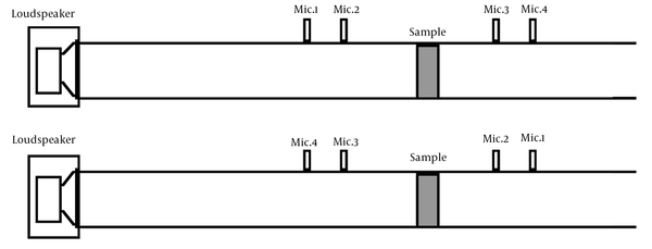
Four-pole parameters or two-source method is based on the transfer matrix (TM) approach (16, 26). This technique is also named the four-microphone method because two microphones are located upstream and two downstream of the acoustical element. A loudspeaker is mounted at one end to generate noise, and an anechoic termination is placed at the other end. The sound pressure levels are measured at the four microphones with two different ends, open or anechoic. A schematic representation of the four-pole method is shown in Figure 1 (28).
The expansion mufflers are used to reduce noise at low frequencies, while it is important that a muffler could diminish noise in a wide range of frequencies. In some typical mufflers used in exhaust systems, several parallel plates (baffles) are utilized for noise reduction, which augments the weight of mufflers. Therefore, it is an advantage that a muffler can reduce and control noise in a wide range of frequencies at a small size and low weight without absorbent material.
2. Objectives
In this study, a double-expansion chamber muffler (DECM) without baffles and sound-absorbing material in small size and lightweight was designed and built. Afterwards, muffler TL was measured, and its acoustical performance was evaluated using the four-pole parameter method.
3. Methods
3.1. Muffler Design
Expansion chambers are all a kind of reactive muffler. In this work, a reflective DECM was designed with equal lengths and an external connecting tube (25). The analysis of mufflers with multi-expansion chambers is mainly performed using the TM approach. Table 1 presents the design principle and equations for estimating the TL of two chambers with equal lengths as an external coupling tube, as shown in Figure 2 (29).
| Step | Equations | Number |
|---|---|---|
| 1. Calculating m | 1 | |
| 2. Calculating the center frequency (f0) | 2 | |
| 3. Calculating k (c = sound speed (m/s)) | 3 | |
| 4. Calculating F1 | F1 = (m + 1)2 cos [2k (L1 + L2)] – (m -1)2 × cos [2k (L2 – L1)] | 4 |
| 5. Calculating F2 | F2 = ½ (m + 1/m) {(m +1)2 sin [2k (L1 + L2)] + -(m – 1)2 sin [2k (L2 – L1)]} – (m – 1/m) (m2 – 1) sin (2kL1) | 5 |
| 6. Calculating TL coefficient (1/αt) | 6 | |
| 7. Calculating TL | 7 |
Equations for Estimating the TL for the Double-Chamber Muffler
The value of L1 is the half-length of the coupling tube (coupling tube length = 2L1), L2 is the expansion chamber length, m = S2/S1 = cross-sectional area ratio for chamber and inlet or outlet tube (the chamber and the coupling tube are assumed to have the same diameter), and K = 2πf/c = wave number.
Based on the intended TL (about 25 dB), the current muffler was designed in 125 - 500 Hz (f1 and f2), and the center frequency was about 312.5 Hz. The constants L1 = 0.075 m and m = 10 were designated according to working conditions in the laboratory. Therefore, D1 and D2 were determined to be 30 mm and 80 mm, respectively. Table 2 shows the parameters of muffler design. To determine the TL of the designed muffler in different frequencies, Equations 1 - 5 and the data in Table 2 were used.
| Muffler Type | D1 (m) | D2 (m) | F1 | F2 | TL (dB) | C (m/s) |
|---|---|---|---|---|---|---|
| Double-chamber | 0.08 | 0.03 | -155 | -723 | 25 | 343 |
Parameters of Theoretical Calculations for Muffler Design
3.2. Transmission Loss Measurement
The technique used in this study was a four-pole method and an impedance tube based on the TM approach. For estimating the performance of parameters on the designed muffler, TL was examined in variable frequencies using an impedance tube. The experimental setup to measure the TL of a double-chamber muffler is schematically illustrated in Figure 3. The experimental principles for designing the desired muffler were as follow:
The muffler TL was evaluated with two-load (open- and closed-ended) and two-source different conditions for precise measurements (30). A type SW477 impedance tube (BSWA Technology Co., Ltd., China) according to ISO 10534-2:1998 (E) (acoustics determination of sound absorption coefficient and impedance in impedance tubes Part 2: transfer function method) was used for this experiment. Two impedance tubes with 100 and 30 mm diameters were applied to measure muffler TL. The frequency range was 63 - 1600 Hz for the larger tube and 500 - 6300 Hz for the small tube. Therefore, the measurements were carried out in third-octave bands of 63 - 6300 Hz.
The setup required two BSWA 1/4” MPA416 microphones before the muffler, two microphones after the muffler with a preamplifier (Type 2670), and a conditioning amplifier (B&K Nexus) in an impedance tube to improve the accuracy of measuring. The interval between microphone holders for the large tube was 80 mm and for the small tube was 22.5 mm. The microphone positions closest to the muffler were 50 and 15 mm for large and small tubes, respectively. The BSWA CA115 microphone calibrator is used to calibrate the microphone signal chain of the system periodically.
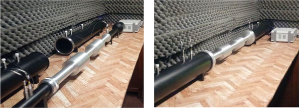
The sound source was a loudspeaker (AUDAX AP100Z0) which gives a random signal consisting of all ranges of frequencies given to the speaker by a data acquisition system (4-channel MC3242) connected to the microphones. The results displayed on a monitor with Frequency Analysis System MC324 were used to convert the acquired data into frequency. The designed muffler inserted between the two connectors allows fixing the muffler with different diameters of impedance tube and sealing the tube to eliminate the acoustic energy exchanged via the flanking transmission pass. The experimental setup for the TL measurement of the muffler is shown in Figure 4.
The ARCAM A65 signal amplifier and a PC equipped with the BSWA VA-Lab software were used to calculate the average responses. The experiments were made in an acoustic room at the temperature and relative humidity of 21°C ± 2°C and 40% ± 5%, respectively. Repeating the experiment three times, the average of measured TL values was calculated, which supports the repeatability of the measurements. The impedance tubes diameter is not the same as the inlet and outlet diameter of the muffler. Consequently, a pair of connectors were used to transition between the impedance tubes and muffler inlet and outlet (30, 31). For the precise measurement of TL, the TL was corrected by subtracting the connectors’ TL.
4. Results
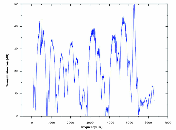
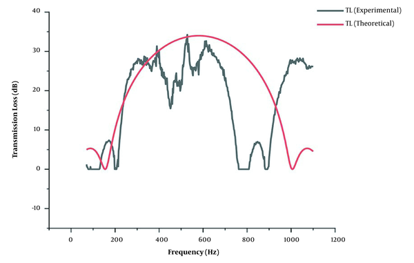
The TL of the muffler, measured using an impedance tube, and the TM method is described in Figure 5. The plot in this figure shows TL versus frequency in the range 63 - 6300 Hz experimentally. The expansion mufflers have different TLs in various frequencies, so the TL has a fluctuated pattern in diverse frequencies. Moreover, the theoretical TL of the designed muffler was calculated using the design data and the equations described in Table 1. To understand the theoretical TL, the results of theoretical calculations for muffler TL at two central frequencies, such as 250 and 312 Hz, are shown in Table 3. Next, the results of the two approaches were compared to evaluate the TL of the designed muffler. The experimental and theoretical attenuation curves against frequency are presented in the range 63 - 1200 Hz in Figure 6. This plot compares the theoretical and measured data obtained from the experiment at 63 - 1200 Hz. The Origin software was used to plot the graph of TL versus frequency.
| Parameters | m | F0 | k | F1 | F2 | C (m/s) | 1/αt | TL (dB) |
|---|---|---|---|---|---|---|---|---|
| f0 = 250 Hz | 10 | 250 | 4.51 | -116.8 | -322.24 | 348 | 73.43 | 18.66 |
| f0 = 312 Hz | 10 | 312 | 5.63 | -153.11 | -689.6 | 348 | 311.88 | 24.94 |
Results of Theoretical Calculations for Muffler TL at f0 = 250 Hz and f0 = 312 Hz
5. Discussion
The TL measurement can be used to evaluate the acoustical properties of the designed muffler, comparing the experimental values of TL with the theoretical data. It is known that the design accuracy can significantly depend on the quality of the theoretical method and the acoustic characteristics of the tested sample. In this study, firstly, a DECM was designed as a reactive or reflective muffler by theoretical equations for noise attenuation in a low-frequency region (125 - 500 Hz) on a laboratory scale to control the noise at the sources producing noise in low frequencies. Secondly, the TL of such a muffler (63 - 6300 Hz) was measured experimentally in a broad frequency range using the impedance tube and 4-microphone technique. Furthermore, the TL of the designed muffler was theoretically predicted using steps 1 - 5 offered in Table 1 for the desired frequency range. Finally, the findings for each approach were compared to determine the design accuracy.
Our findings showed that the TL of the muffler against frequency in the tested frequency spectrum has a trend similar to the theoretical TL pattern of the expansion chambers. The predicted TL demonstrated that the TL of the muffler at 312 Hz frequency had 27.5 dB agreement with the required TL of the muffler or 25 dB. Furthermore, the theoretical equations could be used as a precise method for mufflers design. These results also demonstrated that the multi-expansion chamber muffler could decrease noise in both low and high frequencies. Therefore, the multi-expansion chamber mufflers efficiently reduce noise at a wide range of frequencies. The present study emphasizes the importance of the design principle of mufflers. Designers will easily design efficient mufflers following the steps mentioned above.


