


1. Background
In radiation therapy, precise dose delivery is essential for maximizing tumor control while minimizing damage to surrounding healthy tissues (1-5). A dose bolus is a material placed on the skin surface to increase the dose delivered to shallow tumors, ensuring accurate treatment of superficial regions (6). Traditionally, boluses are made from standardized materials such as Superflab or gel sheets, which are shaped and cut manually to fit the patient’s anatomy. While effective, conventional boluses often suffer from poor fit over irregular body contours, leading to suboptimal dose distributions (7).
Recent advances in 3D printing technology offer the possibility of creating highly customized, patient-specific boluses (8). These 3D-printed boluses are designed based on patient imaging data, allowing for improved conformity to complex anatomical shapes. The potential benefits of 3D printing include better surface dose coverage, reduced air gaps, and the ability to create boluses with varied thicknesses tailored to individual treatment needs (9).
Despite these advantages, it is critical to validate the dosimetric accuracy of 3D-printed boluses before they can be fully integrated into clinical practice. This requires a thorough comparison of their performances against the targeted objectives in terms of dose distribution, homogeneity, and conformity as fixed when creating the virtual boluses with the treatment planning system (TPS). The present study aims at conducting a dosimetric validation of 3D-printed boluses by evaluating their effectiveness in clinical radiation therapy and comparing them to the virtual boluses. This research will assess whether 3D-printed boluses can provide comparable or superior dosimetric outcomes, potentially revolutionizing personalized radiation therapy.
The actual study is the continuation to the first phase of a national research project related to the implementation of 3D printing and modeling technologies for the fabrication of dose boluses used for external radiotherapy at the CLCC of Setif, Algeria (10). After the selection and the characterization of the material to be used for bolus fabrication [thermoplastic polyurethane filament (TPU)], 3 real treatment cases were considered for the dosimetric validation phase related to breast, frontal, and inguinal locations. Indeed, the studied cases were carefully selected to cover some possibilities, where boluses are required for treatment by external radiation therapy. The validation process includes assessing dose coverage, dose profiles across air/bolus/tissue interfaces, dose homogeneity [Homogeneity Index (HI)], dose Conformity Index (CI), and doses received by the organs at risk (OARs). The dosimetric validations were performed under 2 TPSs, “Eclipse” and “Monaco”. The necessary comparison was carried out between the dosimetry of the treatment planning with the virtual boluses created by the clinician and the treatment planning with 3D-printed boluses as placed on the received surfaces and locations. Moreover, the fit of the 3D-printed boluses to the received surfaces were also checked through CT-scanning.
2. Objectives
The main objectives of this study are the following:
(1) Demonstration of the feasibility of producing patient-specific bolus devices using 3D printing, based on virtual designs from the TPS.
(2) Validation of the dosimetric performance of the printed boluses by comparing delivered dose distributions against planned values to ensure accurate target coverage.
(3) Verification of the anatomical conformity by assessing how well the physical bolus matches the patient’s surface geometry via imaging of the bolus-phantom assembly.
3. Methods
3.1. Studied Cases and Treatment Planning
In this study, 3 different boluses were 3D printed by considering external radiation therapy treatment of 3 real cases at 3 different locations, namely: Frontal location, inguinal location, and breast location. For reasons of convenience, the dosimetric verification of the 3D printed boluses was carried out on the Rando anthropomorphic physical phantom in place of real patients. Therefore, the treatment plans for each case were duplicated on the Rando anthropomorphic phantom, considered a physical patient with necessary data introduced to the TPS as it is generally done with a real patient. Therefore, Rando phantom was CT-scanned before and after bolus placement for the different treatment cases and locations considered. Data (CT-slices) of Rando phantom were introduced into the TPS, and the real patients’ radiation therapy treatment plans were reproduced with the same ballistics and contouring (volumes, structures, and OARs). The positioning marks of the Rando phantom were also performed using the treatment simulation scanner, as for the considered real treatment cases. The same boluses of patients were reproduced on Rando with the same treatment plans. The medical physicist, then, performed the different dosimetric checks and verification. The considered treatment cases and locations are presented in the following Table 1.
| Cases | Total Dose/Dose Per Fraction (Gy) | Fields [Energy (MV)/Angulation(°)] a |
|---|---|---|
| Case#1: Frontal bolus | 15/5 | Right anterior oblique [6X*/314] |
| Left anterior oblique [6X/47] | ||
| Right posterior oblique [6X/230] | ||
| Case#2: Inguinal bolus | 46/2 | Left side (lateral) [18X/90] |
| Right side (lateral) [18X/70] | ||
| Anterior [6X/0] | ||
| Case#3: Breast bolus | 40.05/2.67 | Internal tangent [6X/51] |
| External tangent [6X/222] |
Radiation Therapy Plans of the Studied Cases
For the 3D printing, the created boluses were extracted from the TPS, processed by a computer-aided design (CAD) software [SolidWorks (v.2022) and MeshLab (v.2021.05)], and sliced with Ultimaker Cura 5.0.0. Final STL files were transferred to the FDM 3D printing machine “Raise3D Pro2 Plus” for the production of the boluses. The printing conditions are similar to those already presented in our previous publication on the first phase of our research project untaken under grant agreement No 03/18/DFPR/ATRSSV/22 (10).
3.2. Dosimetric Comparison and Validation
The dosimetric validation process includes assessing parameters such as dose homogeneity, dose conformity, dose profile across air/bolus/tissue interfaces, and dose coverage by establishing a dose-volume histogram (DVH) of different volumes [planning target volume (PTV)] and OARs. For such purpose, Rando phantom and boluses were placed at the right position were CT-scanned. The CT data were introduced for a new treatment planning with the 3D-printed boluses placed on Rando. Finally, a dosimetric comparison was carried out between treatment planning with 3D-printed boluses placed on Rando and the treatment planning with the virtual boluses as created first time on the TPS. For this study, 2 types of TPS were used: Eclipse (Ver.18.01) and Monaco (Ver.5.11). Eclipse is a Varian’s widely used system that utilizes beam orientation optimization (BOO) algorithm for dose calculation. Monaco is an Elekta’s TPS that employs the collapsed cone convolution (CCC) algorithm for dose calculation. Both TPSs provide advanced tools for optimizing and calculating dose distributions by ensuring precise and effective radiotherapy treatment planning.
The dosimetric comparison and validation were performed according to the International Commission on Radiation Units and Measurements (ICRU) 83 report which outlines standards and guidelines related to radiotherapy for tumors and constraints on doses to be received by the OARs (11). In this dosimetry comparison and validation, the following dosimetric quantities were considered:
- The minimum D98% and the maximum D2%, D95% and D50% doses received by the planning target volume (PTV).
- The average dose delivered to the PTV.
- The HI, which indicates how the dose is uniform within the PTV, and given by (12, 13):
Where Dp is the prescribed dose intended for the PTV.
- The CI, which evaluates how closely the dose distribution matches the shape of the target volume, and given by (14):
Where VD95% is the PTV that receives at least 95% of the prescribed dose, and VT is the total volume of the PTV.
The dosimetric comparison is also carried out in terms of doses received by nearby critical structures and OARs for the different considered treatment cases and treatment planning in both situations, with 3D-printed boluses and with virtual boluses.
3.3. Bolus Fit to Received Surface Checking
To check if the bolus fits well with the received surface and to perform new treatment planning based on CT-data with bolus in place, Rando phantom with bolus in place was scanned with bolus for each considered treatment case. The CT images were acquired using a Siemens SOMATOM-Definition AS128 scanner and automatically exported to the TPS.
4. Results
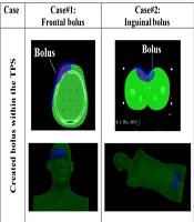
Table 1 presents images of the created and printed boluses for the 3 different treatment cases and locations. The 3D-printed boluses are placed on Rando phantom and CT-scanned to check the right positioning (3rd row). The CT data were also used for treatment re-planning with 3D-printed boluses in targeted places on Rando phantom. As can easily be checked on the figures of the last row of Figure 1, the different boluses fit well with the received surfaces.

Created boluses, 3D-printed boluses, and fit them to the anatomy of the studied cases
Figure 2 shows the lines of profiles of dose across the air/bolus-tissue interfaces. The results clearly demonstrate that in all the studied cases, there are no abrupt dose transitions as in the case of an interface including a heterogeneous medium. The boluses play their role in dose shifting toward depth without any comprise on the normal dose deposition, normal behavior in homogenous medium.

Dose profiles across Bolus and Rando interfaces for the different considered treatment cases and locations demonstrating continuous behavior without brutal changes.
The measured doses received by the PTV volumes with different percentages (D98%, D95%, D50%, D2%, and Dmean) as well as the HI and CI metrics are presented in Table 2 for all the considered treatment cases, locations, and used TPSs.
| TPSs | Plans with Virtual Bolus | Plans with 3D-Printed Bolus | ||||
|---|---|---|---|---|---|---|
| PTV Frontal | PTV Breast | PTV Inguinal | PTV Frontal | PTV Breast | PTV Inguinal | |
| Eclipse | ||||||
| D98% | 37.323 | 37.423 | 9.339 | 37.337 | 37.435 | 9.335 |
| D95% | 38.119 | 38.168 | 9.526 | 38.119 | 38.166 | 9.526 |
| D50% | 40.771 | 41.314 | 10.208 | 40.771 | 40.826 | 10.237 |
| D2% | 42.99 | 42.482 | 10.625 | 42.99 | 42.209 | 10.525 |
| Dmean | 40.661 | 40.884 | 10.157 | 40.194 | 40.544 | 10.210 |
| HI | 0.140 | 0.126 | 0.128 | 0.141 | 0.119 | 0.119 |
| CI | 0.957 | 0.953 | 0.957 | 0.957 | 0.958 | 0.998 |
| Monaco | ||||||
| D98% | 38.125 | 39.340 | 9.866 | 37.806 | 39.221 | 9.970 |
| D95% | 38.967 | 39.808 | 9.962 | 39.019 | 39.672 | 10.034 |
| D50% | 41.505 | 41.300 | 10.312 | 41.530 | 41.080 | 10.284 |
| D2% | 42.610 | 42.141 | 10.542 | 42.706 | 42.183 | 10.532 |
| Dmean | 41.223 | 41.109 | 10.237 | 41.160 | 40.951 | 10.224 |
| HI | 0.112 | 0.069 | 0.067 | 0.122 | 0.073 | 0.056 |
| CI | 0.983 | 0.998 | 1 | 0.975 | 0.998 | 1 |
Dosimetric Comparison Between Virtual Boluses and 3D-Printed Boluses Treatment Planning with Eclipse and Monaco Treatment Planning Systems
When using the Eclipse TPS, D98% and D95% for both situations (designed virtual boluses and 3D-printed boluses) demonstrate almost identical coverage across all PTVs for the different considered cases (breast, inguinal, and frontal), suggesting similar dose coverage. D50% shows minor variation across the PTV, particularly in the breast case, where the 3D-printed bolus shows a slightly lower effective dose at the middle of the PTV (40.826 vs. 41.314). A slightly lower D2% is observed for the 3D-printed boluses, especially for the breast PTV (42.209 vs. 42.482), indicating a lower hot spot. Dmean of the 3D-printed boluses shows a negligible lower average dose across different PTVs, except a slight increase in the frontal PTV (40.194 vs. 40.661). The HI values are largely consistent between the virtual and 3D-printed boluses. The targeted homogeneities on the virtual boluses of the different considered cases were achieved by the 3D-printed boluses. The CI values for the 3D-printed boluses are very close to the values of the virtual boluses, showing good conformity for all PTVs. The slight increase in CI for the breast case (0.958 vs. 0.953) indicates that the 3D-printed bolus fits the received surface better than the virtual bolus.
Likewise, when using Monaco TPS, minor differences in D98% and D95% were observed. For example, for the frontal PTV, D98% of the 3D-printed bolus is slightly lower than that of the virtual bolus (37.806 vs. 38.125). D50% and D2% show slightly higher values for the 3D-pinted blouses compared to virtual boluses. Indeed, D2% for the inguinal PTV is slightly lower with the 3D-printed bolus (10.542 vs. 10.532), suggesting similar dose control as programmed by the clinician on the virtual bolus created within the TPS. The mean dose Dmean is similar across designed virtual boluses and 3D-printed boluses, indicating that the overall programmed dose delivery was achieved by the 3D-printed boluses. The HI of the printed boluses is conformed with that of the virtual boluses with insignificant differences. The CI values of the 3D-printed boluses also show an ideal matching when compared to those of the virtual boluses, especially in the inguinal PTV, where an ideal value of 1 is reported, reflecting perfect conformity with the target.
Doses received by the OARs are presented and compared in Table 3 for the created virtual boluses and the effectively 3D-printed boluses by considering both Eclipse and Monaco TPSs. The doses received by the OARs (eyes, spinal cord, heart, and lungs) are within the limits on dose constraints (15). The HDVs for PTV and OARs are presented in Figures 3 and 4 for Eclipse and Monaco TPSs. The HDVs and extracted dose values between virtual and 3D-printed boluses are quite similar and closely aligned. Therefore, the treatment planning with the 3D-printed boluses all conforms.
| OARs | Eclips TPS | Monaco TPS | ||
|---|---|---|---|---|
| Plans with Virtual Bolus | Plans with 3D Printed Bolus | Plans with Virtual Bolus | Plans with 3D Printed Bolus | |
| Brainstem (DMAX) | 0.617 | 1.001 | 0.818 | 0.893 |
| Right eye globe (Dmean) | 0.618 | 0.390 | 0.919 | 1.707 |
| Left eye globe (Dmean) | 2.499 | 0.951 | 11.213 | 7.557 |
| Spinal cord (DMAX) | 0.169 | 0.082 | 0.136 | 0.401 |
| Heart (Dmean) | 0.477 | 0.479 | 0.988 | 1.075 |
| Right lung (Dmean) | 8.161 | 7.588 | 7.795 | 7.695 |
| Left lung (Dmean) | 0.023 | 0.025 | 0.314 | 0.341 |
| Spinal cord (DMAX) | 0.183 | 0.203 | 0.450 | 0.489 |
Doses Received by the Organs at Risk
![Dose-volume histograms (DVHs) of Eclipse treatment planning system (TPS) for the different considered treatment cases and boluses [virtual programmed (dot line) and 3D printed (solid line)]: A, Frontal; B, right breast; and C, inguinal.](https://services.brieflands.com/cdn/serve/3170b/4817c26f5eeebf513f3d9730ce9f88efdb9e973f/ijcm-159515-i003-F3-preview.webp "Dose-volume histograms (DVHs) of Eclipse treatment planning system (TPS) for the different considered treatment cases and boluses [virtual programmed (dot line) and 3D printed (solid line)]: A, Frontal; B, right breast; and C, inguinal.")
Dose-volume histograms (DVHs) of Eclipse treatment planning system (TPS) for the different considered treatment cases and boluses [virtual programmed (dot line) and 3D printed (solid line)]: A, Frontal; B, right breast; and C, inguinal.
![Dose-volume histogram (DVHs) of Monaco treatment planning systems (TPS) for the different considered treatment cases and boluses [virtual programmed (dot line) and 3D printed (solid line)]: A, Frontal; B, right breast; and C, inguinal.](https://services.brieflands.com/cdn/serve/3170b/91caa91fddfd27e0e3f94c1e735dd2ea294c27c0/ijcm-159515-i004-F4-preview.webp "Dose-volume histogram (DVHs) of Monaco treatment planning systems (TPS) for the different considered treatment cases and boluses [virtual programmed (dot line) and 3D printed (solid line)]: A, Frontal; B, right breast; and C, inguinal.")
Dose-volume histogram (DVHs) of Monaco treatment planning systems (TPS) for the different considered treatment cases and boluses [virtual programmed (dot line) and 3D printed (solid line)]: A, Frontal; B, right breast; and C, inguinal.
The above data and results highlight a high level of compatibility between the effectively 3D-printed boluses and the virtually created boluses (programmed) by the clinician within the TPS. All studied and 3D-printed boluses fit optimally with the received surfaces. The dose profiles across air-bolus-tissue interfaces reveal minimal perturbations, ensuring that the dose delivery remains accurate and effective even in the presence of varying densities. The targeted dose distribution in PTV and the constraints on the dose of the OARs were respected in all studied cases. For both Eclipse and Monaco TPSs, the obtained results demonstrate that the 3D-printed boluses for all the considered treatment cases and locations (breast, inguinal, and frontal) maintain effective dose coverage of the PTV. Values of D98%, D95%, D50%, D2%, and Dmean in PTVs all conform. The CI values are close to one (1) in both used TPSs, indicating the conformity of dose delivery to the PTV with the 3D-printed boluses (16). The obtained HI values indicate that the dose distribution within the PTV conforms to the prescribed dose in all considered cases (12-14). The similarities observed between OARs doses when comparing the programmed virtual boluses to the effectively 3D-printed boluses are certainly due to the powerful and accurate bolus reproduction aspect of the used 3D printing and modeling technologies. Indeed, dose distribution characteristics of the 3D-printed boluses produce similar results to the virtual ones, although the irregular morphology of certain regions and locations. In the studied cases, the overlapping anatomical contours of OARs result in similar dose distribution regardless of the type of bolus used (17). Minor differences observed in mean and maximum doses are not clinically significant. The deviations in terms of doses are within the acceptable limits specified by the clinical protocol, which indicates that 3D-printed boluses are effective in sparing OARs without compromising the treatment efficacy. The observed difference between the two TPSs (Eclipse and Monaco) is due to the used dose calculation and optimization algorithms, resulting in tightly coordinated treatment plans.
5. Discussion
Our study is among several other studies that have shown that patient‐specific 3D‐printed boluses can match planned dose distributions with high fidelity. For example, Zhang et al. reported that 3D‐printed PLA/TPU boluses produced percentage‐depth‐dose curves deviating by < 3% from a water‐equivalent reference (18). Ciobanu et al. similarly found that a custom PLA bolus gave TPS‐calculated and measured surface doses agreeing within ~1% (19). Wang et al. observed that a flexible 3D‐printed chest‐wall bolus delivered skin dose within ~1% of the treatment plan (20). In our work, the TPU boluses achieved virtually identical target coverage and homogeneity (D98%, D95%, HI, CI) to the TPS‐defined (virtual) boluses across all 3 sites. These findings are consistent with the literature, reinforcing that 3D‐printed boluses can reliably meet dosimetric objectives without degrading dose accuracy (18, 19).
Improved anatomical conformity is another common advantage of 3D‐printed boluses. Robar et al. showed that custom 3D chest‐wall boluses significantly reduced large air gaps (max gap ~ 0.3 mm) versus standard flat sheets (7). Malone et al. likewise noted that semi-flexible TPU boluses provided a “highly conformal fit” for head-neck and extremity treatments (21). Similarly, Wang et al. achieved a mean skin-bolus gap of only ~1.0 mm and nearly 100% CI with their 3D bolus designs (20). In our study, the TPU boluses closely matched the frontal lobe, breast, and inguinal contours on the patient CTs, minimizing air gaps and hot spots. Therefore, in agreement with prior reports, we find that patient‐specific boluses improve surface coverage by conforming closely to complex anatomy (7, 21).
Several groups have also demonstrated the clinical feasibility of 3D‐printed boluses. Robar et al. found that most boluses could be printed automatically (median ~ 12.6 h per bolus) and that the improved fit modestly reduced setup time (7). Malone et al. noted that 3D‐printed TPU boluses were “effective and practical” in routine use (21). Importantly, large clinical series have reported acceptable toxicity with 3D boluses: Wang et al. observed that 3D chest‐wall boluses resulted in only mild acute skin reactions (mostly grade 1) in hundreds of patients (20). Consistent with this, our TPU boluses were fabricated in-house on standard printers and applied without difficulty or unexpected side effects. The combination of easy customization and accurate dosing in our cases supports the growing view that 3D printing can streamline bolus production in diverse clinical settings without compromising safety.
Finally, our study uniquely evaluated 3D boluses across two TPSs. We found nearly identical dosimetric outcomes in both Varian Eclipse and Elekta Monaco, implying that the bolus performance is robust to the choice of TPS (prior work typically reports a single TPS). By confirming excellent conformity and dose coverage in 3 disparate anatomical sites (brain/frontal lobe, breast, inguinal), our results extend previous single‐site reports to broader clinical contexts. In summary, these findings reinforce the consensus that 3D‐printed patient‐specific boluses are a viable – and often superior – alternative to conventional bolus materials (7, 21).
5.1. Conclusions
In conclusion, the dosimetric and positioning validation of the 3D-printed boluses for radiation therapy demonstrates their potential to enhance treatment precision, particularly in complex anatomical regions. The conformity of the DVHs for different organs and structures indicates that these boluses can achieve dose distribution homogeneity and conformity within clinically acceptable limits. Furthermore, the analysis of dose profiles across air-bolus-tissue interfaces reveals minimal perturbations, ensuring that the dose delivery remains accurate and effective even in the presence of varying densities. These findings underscore the reliability of 3D-printed boluses in maintaining treatment integrity, offering a customizable and reproducible alternative in radiation therapy. However, further studies may be needed to optimize their design and ensure consistency across complex clinical scenarios, especially for highly heterogeneous regions with open wounds. Therefore, the second phase of the 3D modeling and printing technologies implementation at the CLCC-Setif for the fabrication dose bolus was successively achieved.
