FTIR measurements
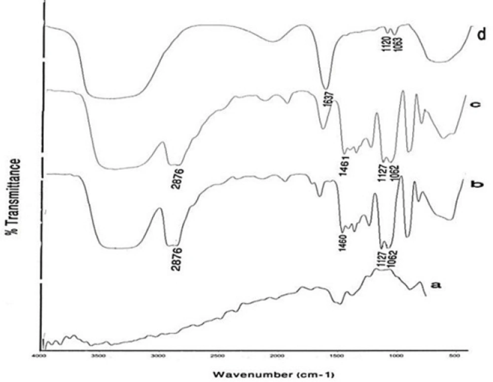
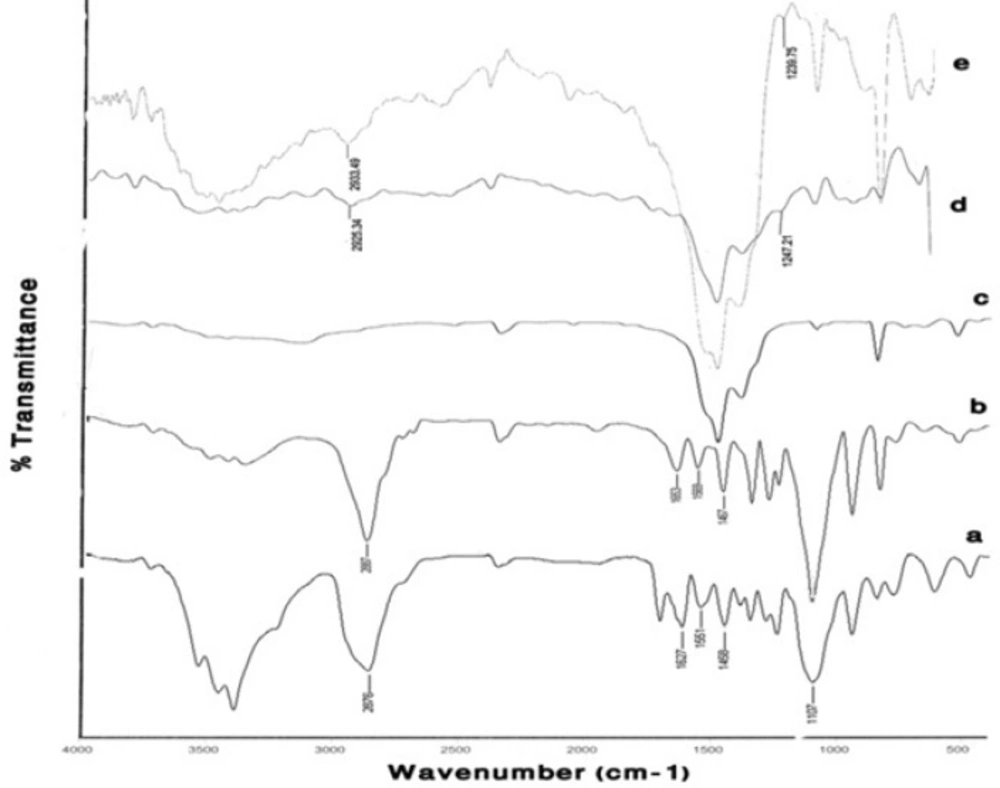
Figure 4 compares the FTIR spectrum of Gd
2O
3 powder, pure DEG, prepared Gd
2O
3-DEG nano crystals before and after centrifugation and dialysis process, in which characteristically different bands of ligands were detected. The bands in pure DEG (spectrum b) at 2876 and 1460 cm
−1 correspond to symmetric stretching and bending of CH
2. The band at 1127 cm
−1 corresponds to C-O stretch, and the broad band of O-H stretch was observed in the 3100–3500 cm
−1 range. FTIR spectra b and c showed similar bands before the supervised polyol rout was applied. After centrifuge and dialysis, however, the FTIR spectrum corresponding to DEG, in the range of 1060-1130cm
−1, diminished and shifted from 1127 to 1120 cm
−1(C-O). Furthermore, the bands at1460 and 2876cm
−1 (CH
2) diminished as well (
Figure 4d).
FTIR spectra of (a) a commercial Gd2O3 powder, (b) Pure DEG, (c) Gd2O3 nano crystals prepared by DEG coating without dialysis and centrifuge, (d) Gd2O3nanocrystals prepared in DEG after dialysis and centrifuge. Curves (c) and (d) depict the effects of the new supervised polyol synthesis route in chemical composition.
Figure 5 compares the results of FTIR spectroscopy for the two different mPEG-saline polymers, SPGO and the PEGylated SPGO nanoparticles (550 and 2000 Dalton). The spectrum of the PEG 550 Da (
Figure 5a) showed characteristic peaks at 1284, 1627, 1107, 2876, 1458, 3100–3500 cm
-1. Some of the strong absorptions of PEG are assigned for the -CH
2CH
2- symmetric stretching and bending around 2876 and 1458 cm
-1(
18,
19)which demonstrate the presence of saturated carbons -(CH
2CH
2)
n-.The Peak at 1284 cm
-1 corresponds to Si–C stretching vibration. The bands at 1627 and 1107 correspond to C=O stretching vibration and C-O ether stretching vibration, respectively. The band at 1551 cm
-1 corresponds to –NH bending vibration in the amide located between the silane and the PEG. Noticeably broad bands in the 3100 and 3600 cm
-1 region indicate exchangeable protons in N-H. Spectra d and e (
Figure 5)belong to SPGO-PEG nanoparticles, whereas spectrum c (
Figure 5) belongs to SPGO before adding PEG. As can be seen, pure SPGO possesses characteristic peaks at 850 and 1500 cm
-1. In addition, two shifts of PEG-silane 550 Da bands’ peaks from 1284 to 1247.21 and from 2876 to 2925 cm
-1(
Figure 5d) were exhibited. It should be noted that the PEG coated SPGO particles were dialyzed before measurements, to remove the excess of PEG polymers (
i.e. PEG polymers that were physically absorbed onto the surface of the particles), and the observed signals, thus only belong to the PEG polymers that are chemically attached. There are only small differences in the FTIR spectrum of SPGO-mPEG-silane 2000 Da compared to that of SPGO-mPEG-silane MW 550 (
Figure 5e).
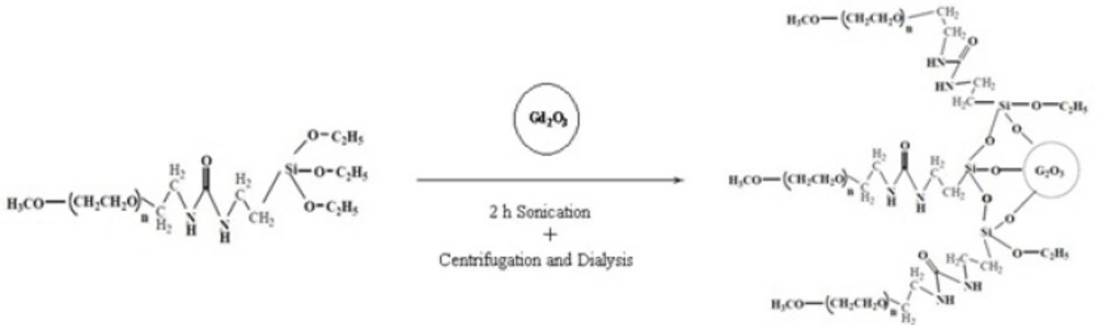
FT-IR spectra of (a) PEG-silane MW 550 powder, (b) PEG-silane MW 2000 powder, (c) a commercial SPGO powder, (d) PEG-silane MW 550 coated Gd2O3 nanoparticles and (e) PEG-silane MW 2000 coated Gd2O3 nanoparticles. Curves (a) and (d), and (c) and (e) show that for PEG-coated Gd2O3 nanoparticles, a silane linker molecule is used to couple the PEG to the nanoparticle
Particle size measurements
Dynamic light scattering (DLS) was used for estimating the hydrodynamic radius of the nanoparticles.
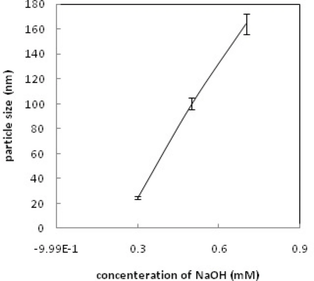
Figure 6 shows relationship between particle size and concentration of OH
-; increasing the concentration of OH
- increases the particle size and leads to rapid precipitation of nanoparticles.
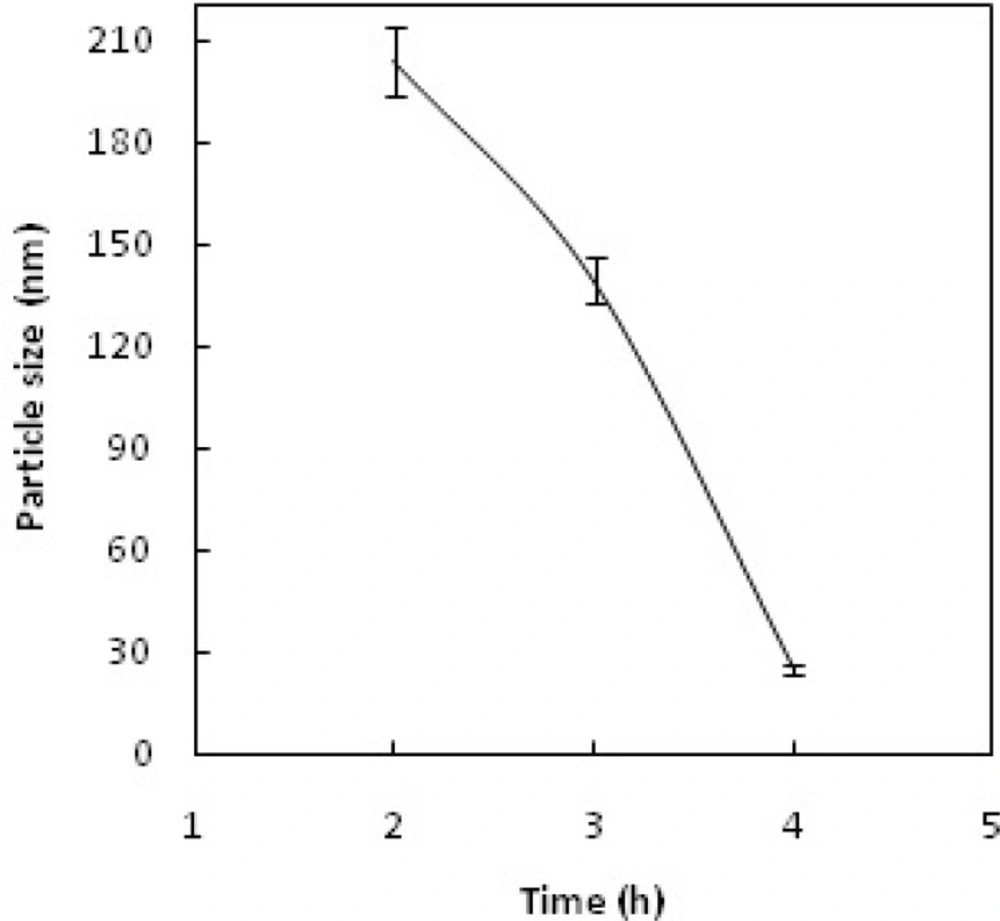
Figure 7 shows the recorded Gd
2O
3-DEG nano crystal sizes as a function of refluxing time in the reaction. The results indicated that increasing the reaction time causes decrease in the size of the nanoparticles(
i.e. the smallest particle sizes were obtained after 4 h reflux).
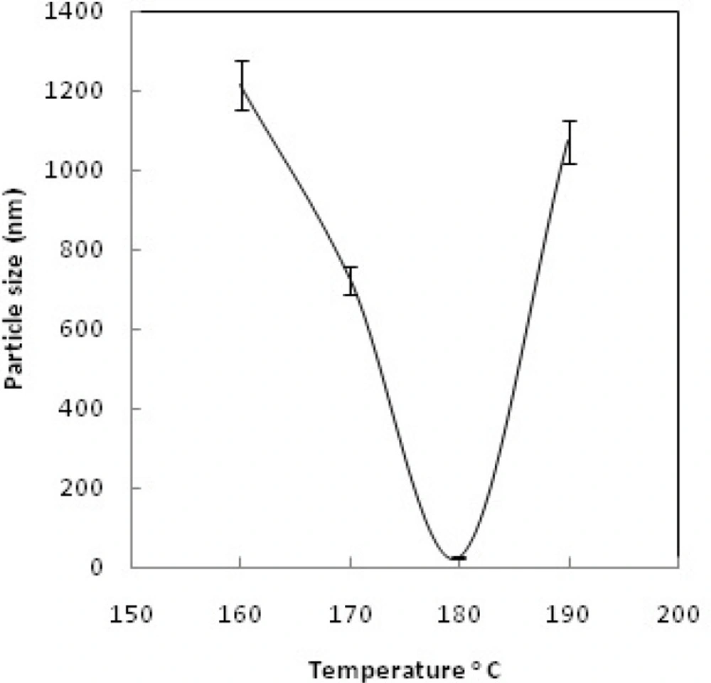
Figure 8 shows the size of the particles relative to the reaction temperature (NaOH 0.3 mM, 4 h). The smallest size was obtained at 180 ºC, while increasing the temperature from 180 to 190 ºC caused aggregation of the particles. nanoparticles in optimization process reached nearly 20 nm in size; still they needed to undergo filtration and dialysis. Thereby, in the optimum reaction conditions, and after filtration and dialysis, the small proper particle size of 5.9 ± 0.13 nm (respective pdI of 0.387) was obtained (
Table 1), compared to the larger size in our previous study(
14).
Particle size vs. OH- concentration.
Particle size vs. reaction reflux time.
Particle size vs. reaction temperature.
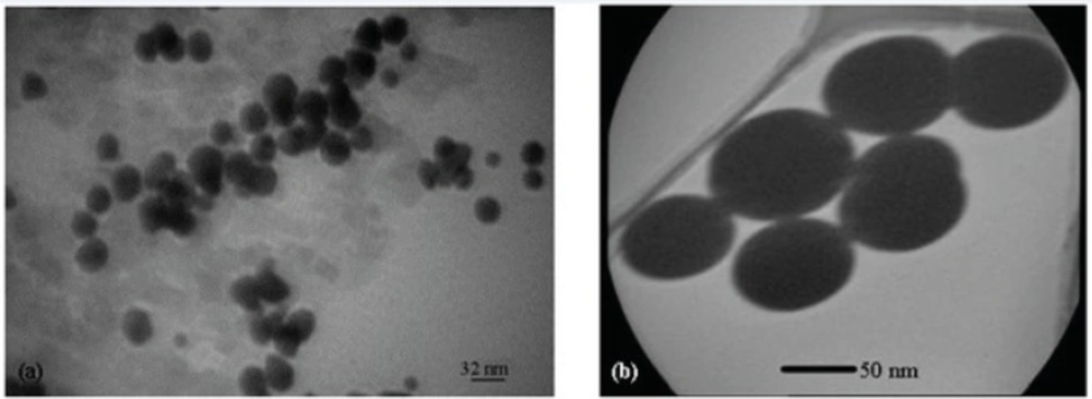
Figure 9 shows the TEM images of Gd
2O
3-DEG nanocrystals, used for hydrostatic size measurements. Gd nanomagnetic particles are clearly formed in uniform spherical or ellipsoidal shapes and visualized separately in nano scaled grains. These findings show that main nucleus (Gd
2O
3 core) is coated by DEG molecules through a strong interaction between DEG with the Gd
2O
3 nanoparticle surface.
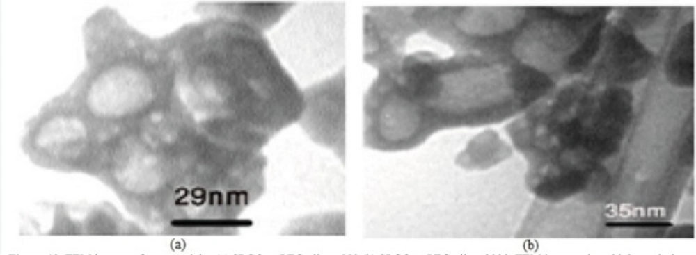
Figure 10 shows TEM images of two other PEGylated nanoparticles, which in contrast to Gd
2O
3-DEG nanoparticles, PEG coated NPMs were not visualized as evidently due to agglomeration and their large molecular weights.
(a) and (b) TEM images of Gd2O3-DEG nanocrystals, showing high resolution images of well uniformed and separated gadolinium nanoparticles after coating by DEG chelates.
TEM images of nanoparticles (a) SPGO–mPEG-silane 550 (b) SPGO–mPEG-silane2000. TEM images show high resolution images of separated gadolinium nanoparticles after coating with PEG chelates. These particles were agglomerated and couldn’t show images as sharp as that of DEG coated particles
Table 1 shows the size and polydispersity index (PdI) measurements using DLS for Gd
2O
3-DEG and SPGO-PEG 550 and 2000 Dalton nanoparticles. Hydrodynamic radiuses of filtered and dialyzed nanoparticles were 51.3 ± 1.46 nm and 194.2 ± 22.1 nm, with PdI of 0.350 and 0.225 for PEG 550 and PEG 2000 coated particles, respectively.
| PdI | Hydrodynamic diameter(nm) | Nanoparticle |
|---|
| 0.387 | 5.9 ± 0.13 | DEG-Gd2O3 |
| 0.350 | 51.3 ± 1.46 | SPGO-mPEG-silane550 |
| 0.225 | 194.2 ± 22 | SPGO-mPEG-silane2000 |
Analysis of magnetic properties
Measurements of magnetic properties were done using VSM and at room temperature.
Figures 11 and
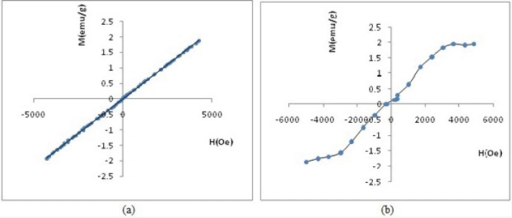
12 demonstrate the relationship between relative magnetization curves and applied field. Removing the applied magnetic field will not lead to coercivity and remanence in paramagnetic, diamagnetic and super para magnetic materials. Paramagnetic materials also have a linear relationship between their magnetization (M) and applied field (H) with positive slope.
Figure 11a vividly shows paramagnetic properties of SPGO particles. Where, Gd
2O
3-DEG nanoparticles exhibited S shape (sigmoidal) Magnetization curve of super paramagnetic materials in
Figure 11b.
(a) Hysteresis loop by VSM of SPGO particles (b) Hysteresis loop by VSM of Gd2O3-DEG
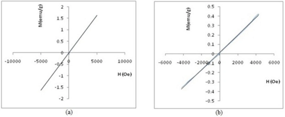
Figure 12 shows the magnetometry of PEGylated nanoparticles. A linear relationship is apparent between magnetization (M) and applied field in this figure, thus, inferring that these two PEGylated nanoparticles are paramagnetic materials. Please note that the susceptibility (as slope of curve) for SPGO-mPEG-silane2000 is less than that of SPGO-mPEG-silane550 (κ
2000=9.20×10
-5 <κ
550=3.28×10
-4).
Hysteresis loop by VSM of (a) Gd2O3-PEG 550 Da nanoparticles and (b) Gd2O3-PEG 2000 Da nanoparticles.
Maximum signal intensities in different concentrations and relaxivity measurements
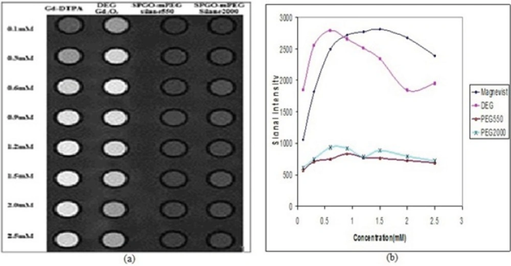
Signal intensity Images and curves for Gd-DTPA, Gd
2O
3-DEG, SPGO-mPEG-silane550 and SPGOm-PEG-silane 2000 using standard spin echo imaging with TR/TE=600/15ms has been presented in
Figure 13. The results of quantitative variation of signal intensities in
Figure 13(b) are in complete accordance with the image visualization in Figure 13(a) for
in-vitro dilutions of the four materials. Concentrations of 0.6, 0.6 and 0.9 mM corresponded to the maximum signal intensities for Gd
2O
3-DEG, SPGO-mPEG-silane550 and SPGO-mPEG-silane2000, respectively.
Table 2 shows the r
1 and r
2 as the slope of R
1 and R
2 relaxation rates versus concentration values for Gd-DTPA, and the three nanoparticles in water.
Signal intensity (a) Images and (b) curves for Gd-DTPA Gd2O3-DEG , SPGO–mPEG-silane550, and SPGO–mPEG-silane2000 in different concentrations, using standard spin echo imaging with TR/TE=600/15ms. The quantitative variations of signal intensities in (b) is in complete agreement with the image visualization in (a), for in-vitro dilutions of the three nanoparticles
| r2/r1( relaxivity ratios) | r2 (mM−1 s−1) | r1 (mM−1 s−1) | Nanoparticle |
|---|
| 1.13 | 5.14 | 4.55 | Gd-DTPA |
| 0.89 | 11.81 | 13.31 | DEG-Gd2O3 |
| 37.62 | 26.34 | 0.70 | SPGO-mPEG-silane550 |
| 33.72 | 33.72 | 1.00 | SPGO-mPEG-silane2000 |
Please note that longitudinal relaxivity (r1) of Gd-DTPA and PEGylated nanoparticles (SPGO-mPEGsilane550
and 2000) were smaller than that of Gd2O3-DEG