1. Background
ECM plays ansubstantial role in cell setting behaviors by influencing on cells through biochemical messages and topography factors and adjusts hemostasis (balance) of the cell.
Reconstruction of the spinal cord and improvement of the function of the isolated neural tissue requires an extracellular matrix to guide the neural cells and the absence of this matrix is the major limiting factor. In vivo, cells are enclosed in three-dimensional microstructures. These structures named extracellular matrix (ECM) are composed of collagen and regulate cells, elastin, and laminin, at the nanoscale level each having its specific bioactive role. ECM plays a considerable role in regulating cell behaviors. In fact, it affects cells through biochemical messages and topographic factors and regulates their homeostasis. In vivo conditioned cells are in a three-dimensional environment and compared to two-dimensional culture, they exhibit different morphology and phenotypic characteristics. Consideringly, a structure similar to the ECM could provide a more suitable environment for directing cells in migration, adhesion and proliferation functions. A 3D model can provide a better sense of the phenomenon occurring in vivo under laboratory conditions. In this space, graphene can be a good substance for scaffolding with the ability of discerning stem cells from neural ones. Recently, graphene and its derivatives have been utilized as constituents of several carbon-based substances including 1D tube-in-tube nanostructures, 2D layer stacked films, and three-dimensional hydrogels (1-4).
Graphene, as one of the carbon allotropes, has different properties than other allotropes or carbon-based compounds e.g. benzene. As a result of these unique properties, the application of graphene in tissue engineering has certain advantages. Its substantial features as low molecular weight, elasticity, electrical conductivity, and adsorption of protein may change the orientation of stem cell differentiation and neural cell proliferation. Another important feature of graphene that is remarkable in tissue engineering is its ability to absorb protein and low molecular weight chemicals. By secreting various substances, cells can grow or communicate with neighboring cells. These materials, after adsorption onto graphene, contribute to cell proliferation and differentiation. Adsorption of lightweight molecules and proteins on the graphene surface occurs through ionic bonding and hydrophobic interactions between nerve and stem cells cultured on graphene (5, 6).
2. Objectives
Materials involved in nerve cell guidance must be able to physically support axonal development and not be toxic or irritating. They should also be viably able to modify and improve the loading site of molecules promoting growth and guidance (7, 8).The effects of graphene oxide aerogel (GOA) when applied to neural cells on their behavior and differentiation will be discussed in detail. Then, the results of cytotoxicity studies on GOA will be presented.
3. Methods
3.1. Materials
Ethylenediamine, natural graphite, and H2SO4 (97%) were purchased from Merck (Darmstadt, Hesse, Germany). KMnO4 (99%), and H2O2 (30%) were provided from Sigma- Aldrich (Saint Louis, MO, USA). Mouse fibroblast cells (L-929) and P19 cells from Genetic Institute of Iran. To get the required material of Trypsin-EDTA, DMEM-F1 (Dulbecco's Modified Eagle's Medium) solution and fetal bovine serum (FBS), we bought them from Gibco BRL laboratories, Germany.
3.2. Synthesis of Graphen Oxide
Graphene oxide (GO) was produced according to Hummer’s method. In this chemical process, natural graphite (1 g) was mixed with H2SO4 (50 mL) in a pyrex reactor with a volume of 10 L. The reactor was fitted with a water cooling system. The mixture was stirred at a rate of 400 rpm for a duration time of 10 min. Afterward, KMnO4 (6 g) was gradually poured on the content of the reactor within 60 min and the prepared mixture was agitated for a duration time of 120 min at a rate of 800 rpm and room temperature. In the following step, using an amount of D.I. water (100 mL, GFL, Germany), the generated suspension was diluted. After that, some amount of D.I. water (200 mL) and H2O2 (6 mL) were poured on the mixture to remove excess metal reactants and ions from the mixture. Consequently, the reaction mixture color was altered from green-brown to a brownish-yellow. Then, through centrifuging at a rate of 6000 rpm for a duration time of 60 min which repeated 4 times, non-target materials such as salts and acids were separated. This step was applied by SIGMA 3 - 18K Centrifuge.The resultant centrifuge top solution then exposed to the ultrasonic waves for a duration time of 30 min. For this step, an ultrasonic bath of Elmasonic was used which adjusted at a frequency of 40 kHz and a power of 150 W. subsequently, the obtained transparent stable aqueous suspension of GO was centrifuged at a higher rate of 2000 rpm for a duration time of 15 min. As the ultimate step, GO suspension was filtered using ashless filter paper circles and the prepared material was placed in a vacuum oven at a temperature of 70°C for a duration time of 24 hours to be dried (9-11).
3.3. Highly Porous Graphene Oxide Aerogel Synthesis
According to the conventional method (12, 13), a homogenous mixture is first made of GO and ethylenediamine and then the mixture is placed in a glass vial and sealed. The glass vial is heated for 6 hours at a temperature of 90°C. This process is aimed at the hydrogel synthesis from functionalized graphene. After the reaction is complete, the process product is washed with a large amount of water to remove the GO that has not entered the hydrogel network. Also, to ensure the withdrawal of non-reacted ethylene diamine, the prepared hydrogel was washed with double distilled water every four hours. This washing process was continued for 48 hours. Finally, the washed hydrogel was placed in a freeze dryer for 24 hours.
3.4. FTIR
In the present study, to detect the bonding and chemical structure of GOA, FTIR spectroscopy of the NEXUS 870 Thermo Nicolet Company in the United States was used.
3.5. Scanning Electron Microscopy
The scanning electron microscopy (SEM) images were captured using the scanning electron microscope (Seron Technology, AIS-2100, Korea), and these examinations were carried out at the room temperature. Before imaging, samples weresputter coated with gold in order to have conductive surfaces. They were coated with Au for 10 min prior to the measurement.
3.6. X-Ray Diffraction
To determine the crystallization percentage of GO and produced GOA and comparing them with each other as well as comparison of crystallization percentage of aerogel, the X-ray diffraction (XRD) spectrum was used. For this purpose, the machine made by model EQUINOX3000 Inelcompany, from German country, was used and the samples were checked by the use of X-ray at 40 KW and 30 mA, and 900 Watts. The range of angles studied was 5 to 30 degrees.
3.7. MTT Assay
For the cytotoxicity test of the MTT, we selected the L929 mouse fibroblast cells. First, a general examination was performed on the cells to ensure their proper condition. This task was carried out via observing the cell count, the morphologic structure of the flask containing the cell, and culture medium.
In this study, the principal requirement was the viability of the L929 cells based on the standard number ISO10935. In order to sterilize the samples, they were first exposed to UV rays. Cell concentration was adjusted to 1 × 10⁵ cell/mL. Moreover. Placement of the scaffolds was in a triplicate in 24 well plates, and 1 mL of cell suspension was added to each well. Since a total of 3 wells were designated for the control group, they did not receive any scaffolds. The incubation of the samples was carried out with 5% CO2 in the atmosphere and at 37°C. The incubation cell was washed after 24 hours using a PBS solution. Moreover, 100μL of MTT solution (i.e. 5 mg/mL) was added to each well and another 4 hours of incubation were followed after this addition.
3.8. Fibroblast Culture
During some in vitro cell culture trials, the reaction between the cell culture and the scaffold was examined. L929 mouse fibroblasts were utilized in this investigation and cultured in RPMI containing penicillin (100 µg/mL), fetal calf serum (10%) and streptomycin (100 µg/mL). Before seeding, a suspension of 1.8 × 10⁵ cells/mL was supplied. Before culturing the cell, two specimens were provided for each scaffold sample by sterilizing in ethanol (70%) and washing in the culture media. The samples were put on a plate of multiwall polystyrene accompanying the cell suspension (5 mL) and maintained in a CO2-controlled incubator with a temperature set at 37°C for 48 ± 1 hours. As a negative control, one of the samples was held on. At the end of the incubation period, all of the samples were washed with the phosphate-buffered solution of saline. Exploiting glutaraldehyde 2.5%, the cells were fixed and finally were dehydrated utilizing graded ethanol as 60%, 70%, 80%, and 95%.
3.9. Culture of P19 Cells
P19 cell line from mouse (C422) was supplied from Genetic Institute of Iran. In order to gain a density of 5 × 10⁴ cell/mL, the cells were cultured and preserved in accordance to Rudnicki and McBurney (14). Then the cells were separated mechanically from the culture dishes and laminated into 100-mm bacteriological grade Petri dishes comprising a medium of α-MEM. This medium was supplemented with 0.3 μM retinoic acid (RA) and 10% calf serum to prompt neural P19 cells differentiation and growth as aggregates. After an incubation time of 4 days, a volume of cell suspension (1 mL) with the concentration of 5 × 10⁴ cell/mL was seeded in 24 well tissue culture plate from polystyrene comprising scaffolds which cultured in a medium at a temperature of 37°C, without RA and containing CO2 (5%) and environmental humidity (95%) for a duration of 10 days. Before than cultivation, exposing to UV radiation for a duration time of 120 min, the scaffolds were sterilized and subsequently washed 3 turns with sterile PBS. Each of these washing steps lasted 20 min. Gently evacuating the medium and removing dead cells through washing the scaffolds for a duration time of 5 min led to the stabilized grown cells. Aiming the cell fixation, glutaraldehyde solution (2.5 V/V%) was subjoined to every well. Plates were kept at room temperature for a duration time of 120 min.Within 5 min, the samples were washed using phosphate-buffered saline (PBS) and dehydrated by immersion in a sequence of ethanol solutions of varying concentrations as 50, 60, 70, 80, 90, 100 v/s%. The immersion time in each ethanol solution was 5 min. Afterthat, the samples were washed again the solution of with phosphate-buffered saline (PBS) for 5 min. After eliminating PBS, the scaffolds were completely dried at room temperature for 24 hours (15). The surfaces of tissue culture plastic was considered as the negative control. Light microscopy imaging were performed by T-FL optical microscope (Nicon model, manufactured in Japan) to examine the murine P19 cells differentiation in the matrix of scaffolds. All of the biological experiments were repeated at least three times.
3.10. DAPI and Immunofluorescence Stainings
Using DAPI (4-6-diamidino-2-phenylindole) as a blue fluorescent probe, the nuclei of cells were stained. DAPI can bind with DNA of fixed live cells which lead to specific fluorescent complexes with very high intensities. Cell staining were carried out through the following steps: washing the scaffolds with PBS for 5 min; applying DAPI solution with the concentration of 1:1000; washing the scaffolds three times with PBS. Each washing step lasted 5 min. Cells labeled with this antibody and nuclei stained were examine using optical microscope and their images were captured. Generally, the existence of cells on the scaffold can be evidenced through this method. In addition, in order to confirm the differentiation of P19 cells on the scaffolds, immunofluorescence staining we carried out. After a week of seeding the cells, the samples were translocated to gelatin-coated dishes and using a solution of paraformaldehyde (4%) in PBS for 30 min they were fixed at room temperature. The specimens were washed in PBS three times. Each of these washing steps lasted for 5 min each. With the aim of obtaining more permeability, the cells were exposed for 45 min to Triton-X (1%) diluted in PBS. Afterthat, the cells were blocked using fetal bovine serum (FBS) (5%) in PBS for 5 hours. Followingly, the samples were incubated overnight with MAP-2 (Microtubule associated protein-2) antibody (1:100) at the temperature of 4°C. The mentioned protein is a particular protein existing in neural cells. Subsequently the cells were washed using PBS three times which any of washing turns lasted for 5 min (16).
4. Results and Discussion
4.1. FTIR
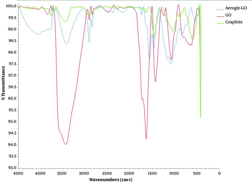
Figure 1 shows the absorption peaks originated from oxide groups localized on GO. The peaks appeared in 3443 cm-1 is related to flexural (bending) vibrations of O-H group; in 1746 cm-1 belongs to tensile vibrations of C=O groups in carbonyl and carboxyls; in 1638 cm-1 reveals tensile vibrations of aromatic carbon C=C; in 1236 cm-1 indicates tensile vibrations of the carboxyl group of C-O existing in –COOH; in 1071 cm-1 denotes the tensile vibrations of epoxy groups (1 and -2 ether), and finally the peak appeared in the wavenumber of 665 cm-1 is attributed to the change in the form of the C-H group attached to C=C. The presence of these functional groups causes the GO polarization, which justifies the ease of homogeneous distribution in the water.
Figure 1 shows the FT-IR spectra of GOA. Moreover, a slight intensificationof the peak at 1089 cm-1 was also observed after ethylenediamine grafting on GOA. After GO reduction by ethylenediamine, a significant decline occurred in the intensities of the peaks rised from the oxygenated functional groups. For example, the peak of –OH deformation vibration appeared at 3427 cm-1 shows this tendency. The new peaks appeared in the region of 1568 cm-1 and 1160 cm-1 is assigned to the strong in-plane C–N scissoring absorption and C–O stretching vibration, respectively (17-19).
4.2. Scanning Electron Microscopy
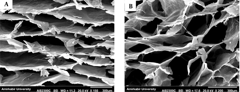
Figure 2 shows the SEM images of GOA (graphene oxide aerogel) sheets. Obviously, a honeycomb-like cellular structure can be seen. The cell walls are composed from assembled graphene sheets produced through the freezing step. At this step, the individual sheets are pressed together to form ice crystals. The in-plane size of these integrated sheets can be up to several tens of micrometers. Leading to an enhanced elastic stiffness. This assembling is led to a well-defined and interconnected 3D porous network with increased elastic stiffness.
4.3. X-Ray Diffraction
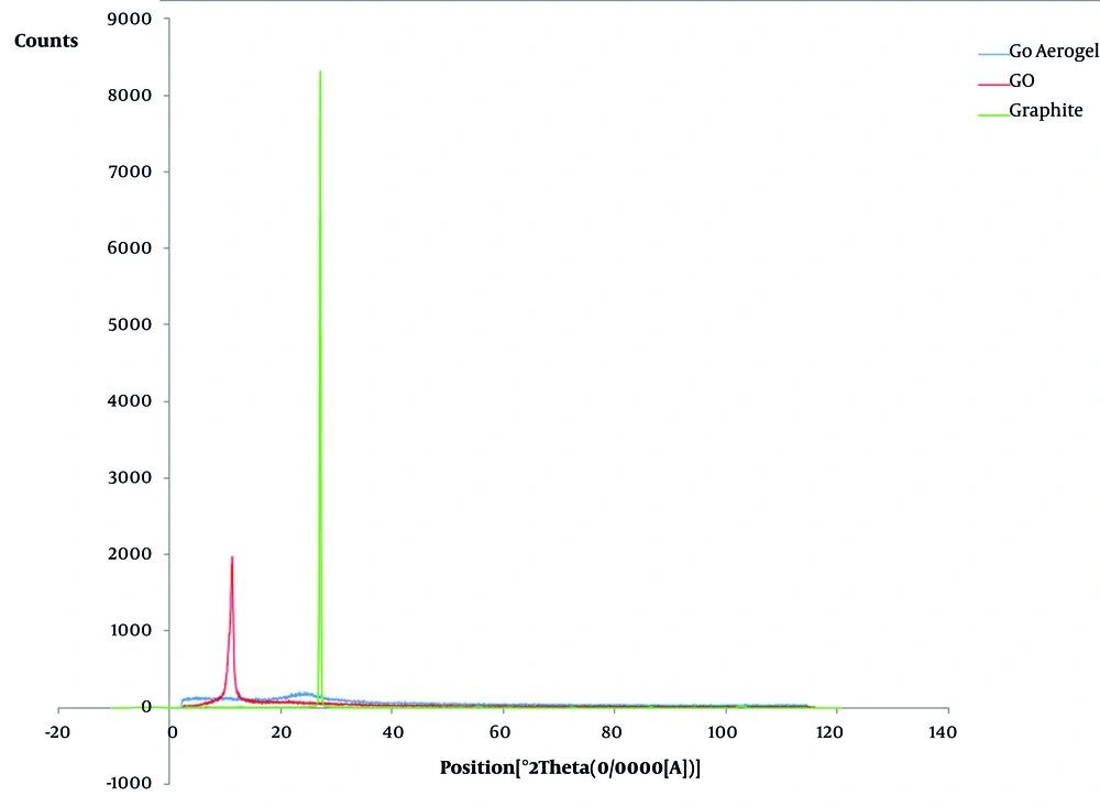
Figure 3 shows the X-ray diffraction patterns of graphite, GO and GOA. According to literature, the natural graphite displays a basal reflection peak (002) at 2θ = 27.168° with a d-spacing value of 3.282°A (20). However, after oxidation, the mentioned (002) reflection peak was shifted to 2θ = 11.148° with a d-spacing value of 7.936°A. This shift indicates the intercalation of oxygen functional groups to the graphite basal plane (21). In the XRD pattern of GOA, a new wide peak appears at 2θ = 23.9 (d-spacing 3.717°A) indicating GO sheets reduction and the separation of sheets accompanying EDA attached to them (13). These results propose the role-playing of π-π stacking between the graphene sheets in the graphene aerogel and the inhomogenous graphite-like carbon crystalline state (22).
4.4. MTT Assay
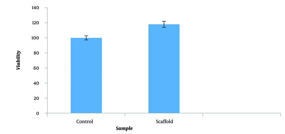
The results from the MTT test on scaffolds following 48 hours of culturing of the cells are demonstrated in Figure 4. In specific, the cell’s survival ratio on the scaffolds was measured using the formazan absorption rate. The cell’s growth ratio can be seen at 570 um wavelength in the diagrams illustrated. Cell viability of 100% is a standard value for the nontoxicity of the biomaterial samples. All the samples produced in this study were biocompatible after 48 hours. This biocompatibility implies a lack of toxicity in L-929. The scaffold’s cell viability and the L-929 cell contact were 118%.
4.5. Cell Culture
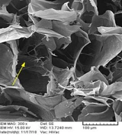
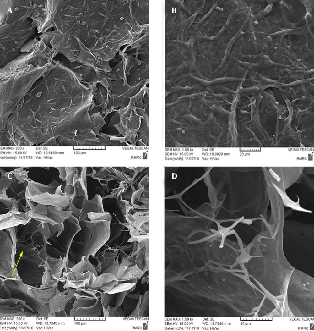
The SEM images clearly display the overall structure, interaction, and adhesion of cells to the samples. The interconnection between cells is well demonstrated in the scaffold image. It is more difficult to take appropriate images in the scaffolds due to their porous structure and the penetration of cells therein. Figure 5 shows the penetration of cells into the porous structure. It should be noted that it is difficult to distinguish the cells from the surface roughness due to the nonuniform scaffold surface. Nonetheless, high-quality images were reported herein.
4.6. Culture and Differentiation of P19 Cells
SEM images were examined which are shown in Figure 6. These images can demonstrate the interaction between scaffolds and differentiated P19 cells after 14 days of cell culture. According to these studies, it can be said that the neurons of embryonic stem cells (ESCs) can be differentiated on the support of structures having suitable biological and chemical behavior. Thanks to their ability for differentiation into neuronal groups, ESCs can be utilized on scaffolds to restore neural damage. This study demonstrates that the scaffold synthesized in the proximity of differentiation factors could be a better substrate for ESCs neural differentiation. However more explicit tests and functional investigations need to be performed to prove these findings. The results of these experiments demonstrate that the designed scaffold may facilitate ESCs differentiation into more effective neurons.
4.7. Immunofluorescenc
Figures 7 and 8 show that the cells marked with MAP-2 antibodies could be observed under a microscope. Bright green phosphorus areas show a positive reaction against their specific antibodies due to the presence of MAP-2 proteins, which were observed and recorded by the microscope. The presence of this protein, specific to neuronal cells, proves that P19 cells were successfully differentiated into neurons after the cell culture process.
Figure 8 illustrates the cell differentiation into the scaffold by immunochemical staining technique for neuron-specific protein marker as MAP-2 (microtubule-associated protein 2) antibody. Cells were fixed in different development stages and stained using anti-MAP-2. The morphology of the cells stained with this antibody is shown in Figure 8. It confirms the differentiation of P19 cells into neuron cells. At the end of 14 days cultivation, the staining of MAP-2 was acquirable on the surface of the scaffold. The cells on the scaffolds were extremely immunopositive for MAP-2. In our study, we have shown that GO scaffold is a proper choice for P19 cell adhesion and differentiation to neural cells.
In Figures 7 and 8, the green phosphor dots are the points with a positive response due to the presence of MAP-2 protein against its special antibody. This confirms that P19 cells of mice in the course of the cell culture steps have been differentiated well into neural cells. Alongside the positive response of cells to the staining, the intensity of this reaction is also considerable. Considering the large count of green dots in the images of immunofluorescence staining, it can be said that a large number of murine P19 cells can be differentiated into the nerve cells.
More interestingly, since cell differentiation was about 16% on the control surface and about 89% on the scaffold surface, P19 cells were effectively differentiated into neural cells, indicating the effective role of GOA in neuronal differentiation.
More interestingly, the cell differentiation rates of ~16% and ~89% respectively on the control and the scaffold surfaces, P19 cells were effectively differentiated into neural cells, indicating the effective role of GOA in neuronal differentiation.
5. Conclusions
In this study, sample was assessed considering the physical, morphological, and mechanical characteristics as well as the cultivation of L-929 fibroblast cells and differentiation of P19 cells. Morphological examination using images of the scaffolds captured by a scanning electron microscope (SEM), disclosed the three-dimensional (3D) structure which has a lot of pores prior to mounting cells on. Based on dynamic-mechanical thermal analysis (DMTA) data, the prepared scaffold has a great storage modulus. L-929 fibroblast cells were utilized to evaluate the appropriateness of the scaffold and its cellular interaction. It was demonstrated that P19 cells could be differentiated on the surface of the scaffold. In a duration of 14 days, a highly viable, congruent, and interconnected neural network was built through a biocompatible route on the scaffolds. Further studies should be performed on the control of P19 cell growth as well as predicting the potential of utilizing these substances in neuronal repairing with the aim of evaluating the architecture and roughness and consequently the compatibility of these scaffolds.
