Considering a docking based on HADDOCK, we constructed the structural model of an IR homodimer/insulin complex in the presence of insulin pdb file (code: 3INC) and homology modeling based on 3LOH and 3W11 PDBs.
Our built model showed new salt bridges (i) Asp17 salt bridges to Arg554 (F1), the same residue salt bridges to Lys 484 (F1) (ii) the side chain of Lys50 salt bridges to Asp707 (α-CT) (
Table 2 and
Figure 2) (iii) the side chains of Asp499 (F1) interacted with Arg371 (L2) (iv) while the side chain of Arg345 (L2) interacted with Asp535 (F1) (v) the side chain of Lys166 (L1) interacted with Asp645 (F2) (
Table 3 and
Figure 3).
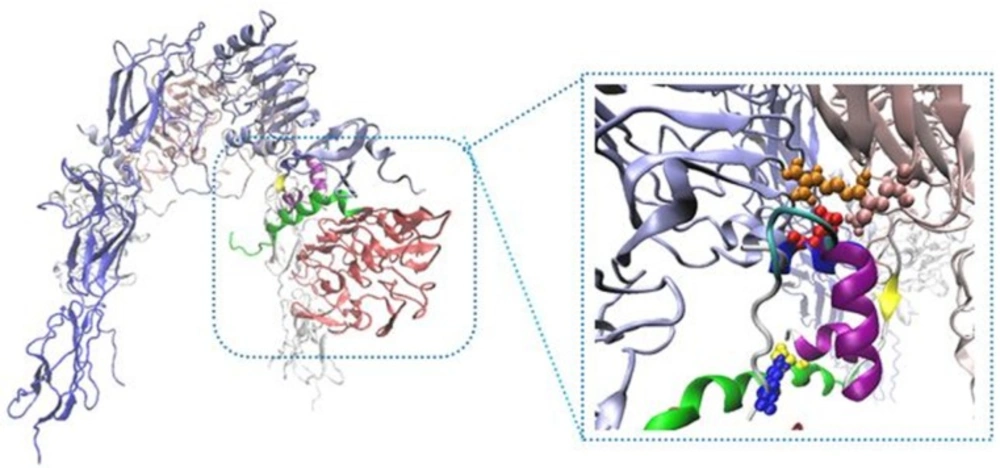
New Cartoons, and the A- and B-chain of insulin are secondary structure NewCartoons. New salt bridges between insulin and its receptor depicted as vdw (zoomed view). Blue vdw indicates K50 on insulin which interact with D707 (α-CT; yellow vdw), red vdw corresponds D17 on insulin had salt bridge with R554 (F1; orange vdw) and K484 (F1, pink vdw).
To survey the important role of salt bridges, rigid parts 2 and 3 resulting from HingeProt were added as two separate PDB files. To keep the distance between the mentioned rigid parts in the range of covalent bond, i.e., 1.4 ± 0.2, a restraint was defined in their connected hinge and three restraints defined for salt bridges between rigid part 3 and rigid part 1 (L1) of opposite monomer. Following docking, the distance between two rigid parts was in the range of 50 Å indicating the power of salt bridges to expose rigid part 3 towards L1 on the opposite monomer (
Figure 4).
To tackle this high distance, rigid part 2 and 3 were added as a complete PDB file. In spite of the distance between two rigid parts kept, there are not any conformational changes in the second structure of these rigid parts. To survey this event more accurately, the restraints that indicate salt bridge on rigid parts 2 and 3 were ignored. Then rigid parts 2 and 3 were added continually and docking was done in the same state. The new docking results display that their distance was about 4 Å, but instead of the formation of inverted V structure, L shape was occurred (
Figure 5).
These results indicated the importance of salt bridges to form an inverted V shape of IR. On the other hand, we suggest that the force which created space between rigid parts 2 and 3 during the application of salt bridges causes to pull rigid part 3 to extracellular regions and to transfer a force to intracellular parts; therefore these processes activate intracellular signaling pathways.
With regard to the importance of α-CT, at first we focused on α-CT role in the complex of IR/insulin homodimer. Residue His710 contains a resonance structure and structural stability relative to the around residues, i.e., Asp707-Tyr708, 714, so His710 has the lowest affinity to create bond and also to participate in the interaction; the amount of affinity became too low especially in the presence of insulin.
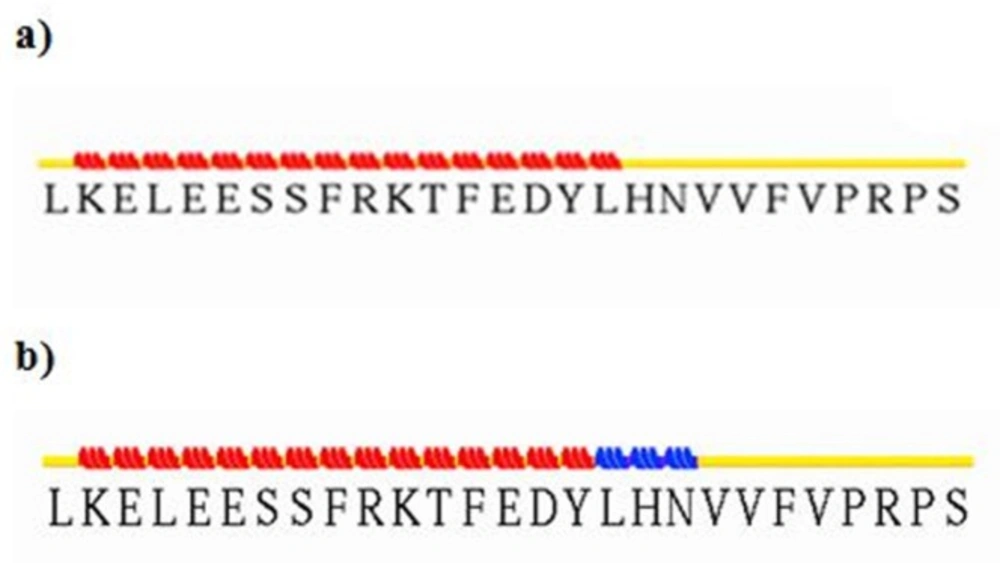
To elucidate secondary structure changes, stride server was used. In our results, turn and random coil were converted to extended beta sheet which took place in the most parts of the complex of insulin and IR dimer (
Figure 6).
Mode 1
|
|---|
| Rigid Part No | Residues | Score |
|---|
| 1 | E: 4-457 | 0.98 |
| 2 | E: 458-655, 693-710, 755-909 | 0.97 |
Hinge residues: 457E
|
Mode 2
|
| Rigid Part No | Residues | Score |
| 1 | E: 4-254 | 0.98 |
| 2 | E: 255-598 | 0.96 |
| 3 | E: 599-655, 755-909 | 0.96 |
| 4 | E: 693-710 | 0.78 |
| Interaction sites | Distance (Å) |
|---|
| D17-R554 | 2.68 |
| D17-K484 | 2.64 |
| K50-D707 | 2.62 |
| Interaction sites | Distance (Å) |
|---|
| D499-R371 | 2.73 |
| R345-D535 | 2.59 |
| K166-D645 | 2.66 |
Sequential docking methods
|
|---|
| Name | segment ID | experimental Active residue
| number of interaction of HADDOCK predicted active site & experiment | the number of new predicted active site by HADDOCK |
|---|
| Resid | number |
|---|
| Rigid part 1 (1th monomer) | A | 32,34,36,37,39,65,62,64,88,89,94,96,120,124,153,154,247,246,248,254 | 20 | 17 | 85% | 5 |
| Rigid parts 2,3 (1th monomer) | K | 454,394,780,804,282,256,25,255 | 8 | 7 | 88% | 34 |
| Rigid part 4 (1th monomer) | J | 705,708,709,712,713 | 5 | 5 | 100% | 8 |
| Insulin | D | 28,29,30,31,32,33,34,35,36,37,38,39,40,41,42,1,2,3,4,19,12,13,14,17 | 24 | 16 | 66% | 11 |
| Rigid part 1 (2nd monomer) | I | 247,246,248,254 | 4 | 4 | 100% | 10 |
| Rigid parts 2,3 (2nd monomer) | E | 484,552,591,602,616,620,62,780,804 | 9 | 6 | 66% | 12 |
Sequential docking method
|
|---|
| Step 1 | Step 2 | Step 3 | Step 4 | Step 5 | Step 6 |
|---|
| HADDOCK score | -103.7+/-2.7 | -119.8+/-1.9 | -73.5+/-1.4 | -57.0+/-2.2 | -108.3+/-8.2 | -231.6+/-7.0 |
| Cluster size | 64 | 129 | 198 | 200 | 191 | 200 |
| RMSD* | 0.8+/-0.5 | 0.4+/-0.2 | 0.4+/-0.3 | 0.3+/-0.2 | 0.6+/-0.5 | 0.5+/-0.3 |
| VDW energy | -47.9+/-6.6 | -75.8+/-5.2 | -58.4+/-5.3 | -30.8+/-1.1 | -55.4+/-4.8 | -114.4+/-12.7 |
| Electrostatic energy | -142.4+/-25.5 | -142.1+/-61.3 | -323.2+/-20.0 | -83.2+/-30.4 | -200.0+/-29 | -1003.7+/-12.1 |
| Desolvation energy | -39.1+/-6.0 | -36.1+/-11.1 | 1.2+/-4.0 | -10.2+/-5.2 | -24.7+/-10 | 74.2+/-14.9 |
| Restraints violation energy | 117.7+/-46.85 | 205.9+/-54.56 | 482.7+/-3.36 | 5.9+/-0.17 | 119.0+/-7.77 | 93.6+/-24.43 |
| Buried Surface Area | 1541.3+/-42.8 | 2028.6+/-62.6 | 2075.4+/-98.3 | 861.1+/-36.9 | 1652.0+/-59.3 | 5280.1+/-161 |
| Z-Score | -1.3 | -2.5 | 0.0 | 0.0 | -1.0 | 0.0 |
RMSD from the overall lowest-energy structure.
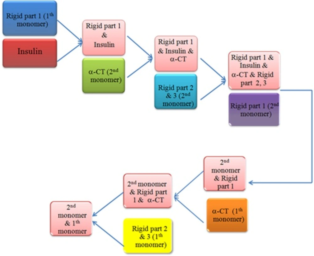
Work-flow of sequential docking process. After disruption our receptor by HingeProt, each part was uploaded in HADDOCK and the best solution resulted from each process was used for the next step. Rigid part 1: L1 domain of insulin receptor, Rigid part 2 & 3: FnIII-1 and FnIII-2 of insulin receptor
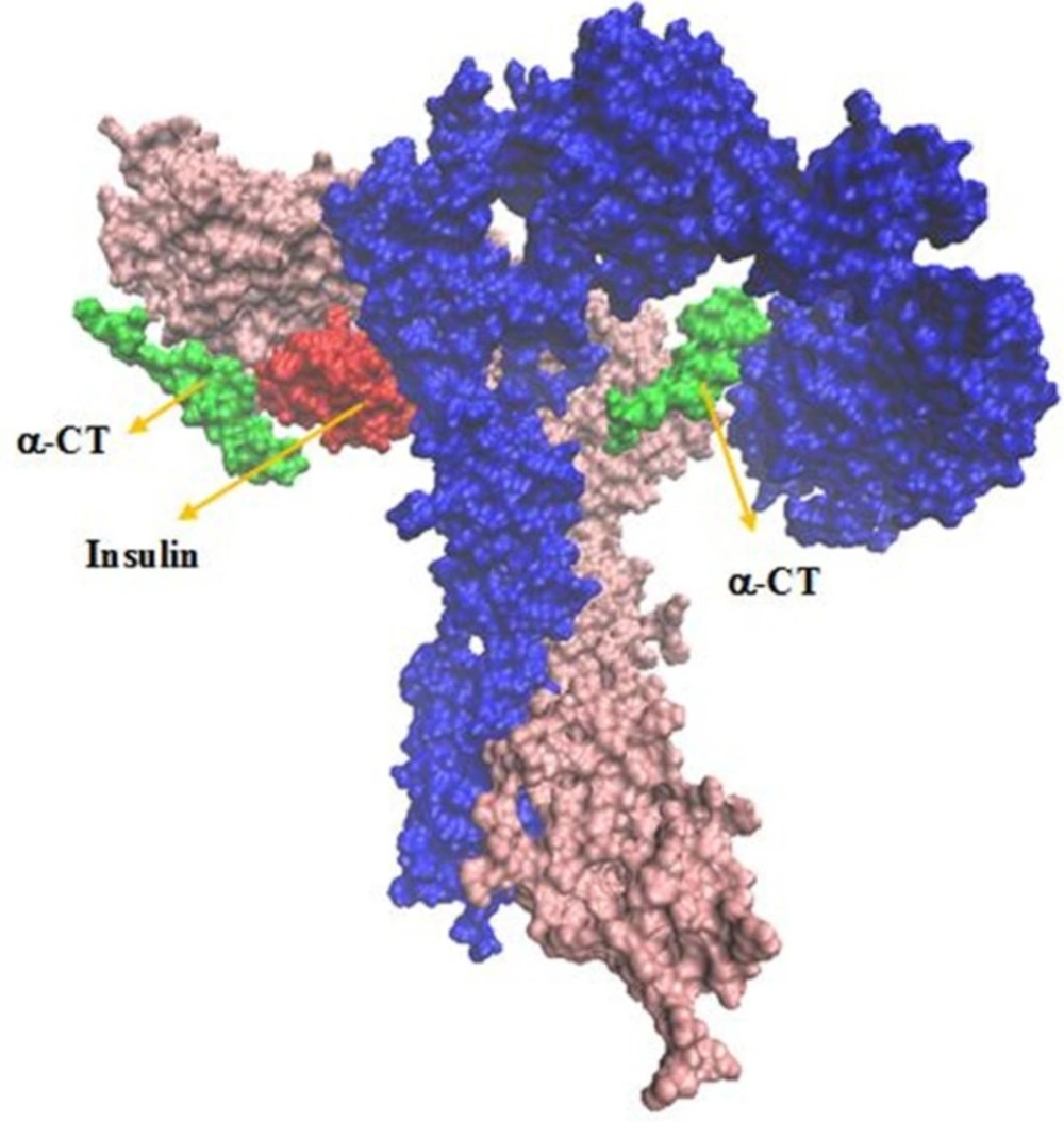
The interaction sites between insulin and IR. Receptor domains are shown in opaque
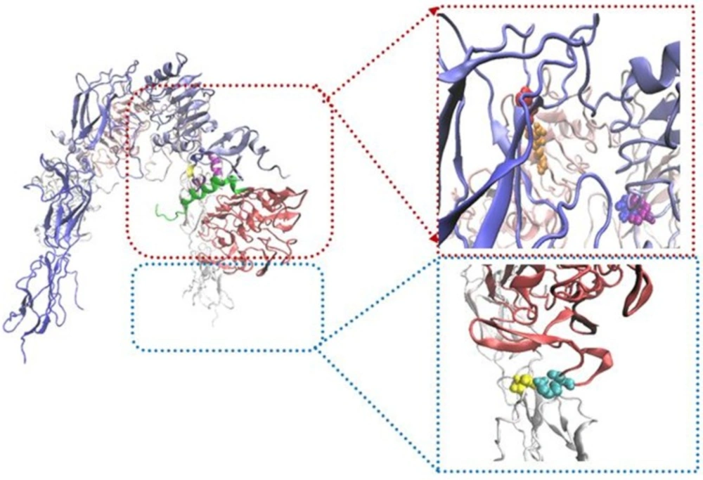
Schematic illustration showing location of salt bridges. In the right panels, salt bridges represent between R345 (L2; purple)-D535 (F1; blue), K166 (L1; cyan)-D645 (F2; yellow) and D499 (F1; red)-R371 (L2; orange
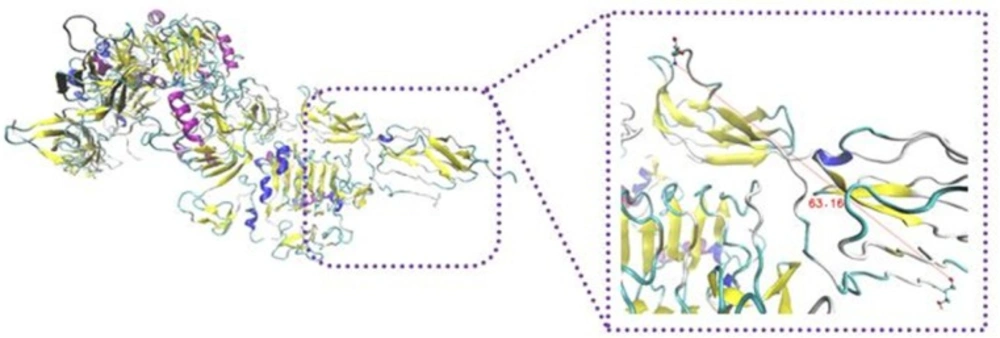
Schematic illustration of IR/insulin homodimer sequential docking approach. Distance between the mentioned regions were more than 50 Å, a restraint was defined in their connected hinge. It describes the power of salt bridges to expose rigid part 3 towards L1 on the opposite monomer
Schematic illustration of IR/insulin complex sequential docking method. Rigid parts 2 and 3 were added continually. The following docking, distance between these regions were about 4Å, but it displayed L shape instead of inverted V
Input and output files of -CT in complex with L1 resulting from stride server. In the input file, residue Leu709 contain -helix structure, but residues His710 and Asn711 have turn shape. The following participation in the complex, residues 709-711 were converted to 310-helix. It looks that the conformation gets extended relative to before docking
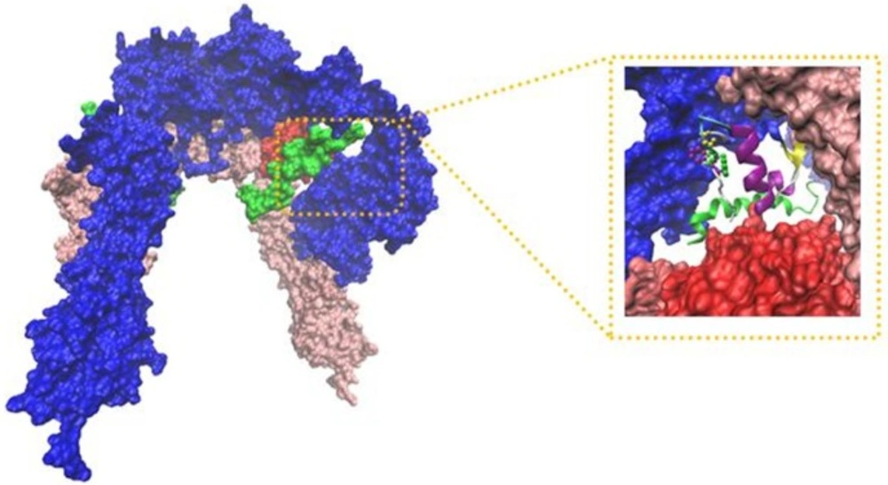
The IR ectodomain homodimer, showing the attached of insulin sequential docking approach. Red arrows in the right part of figure indicate viewing directions for insulin and CT peptide
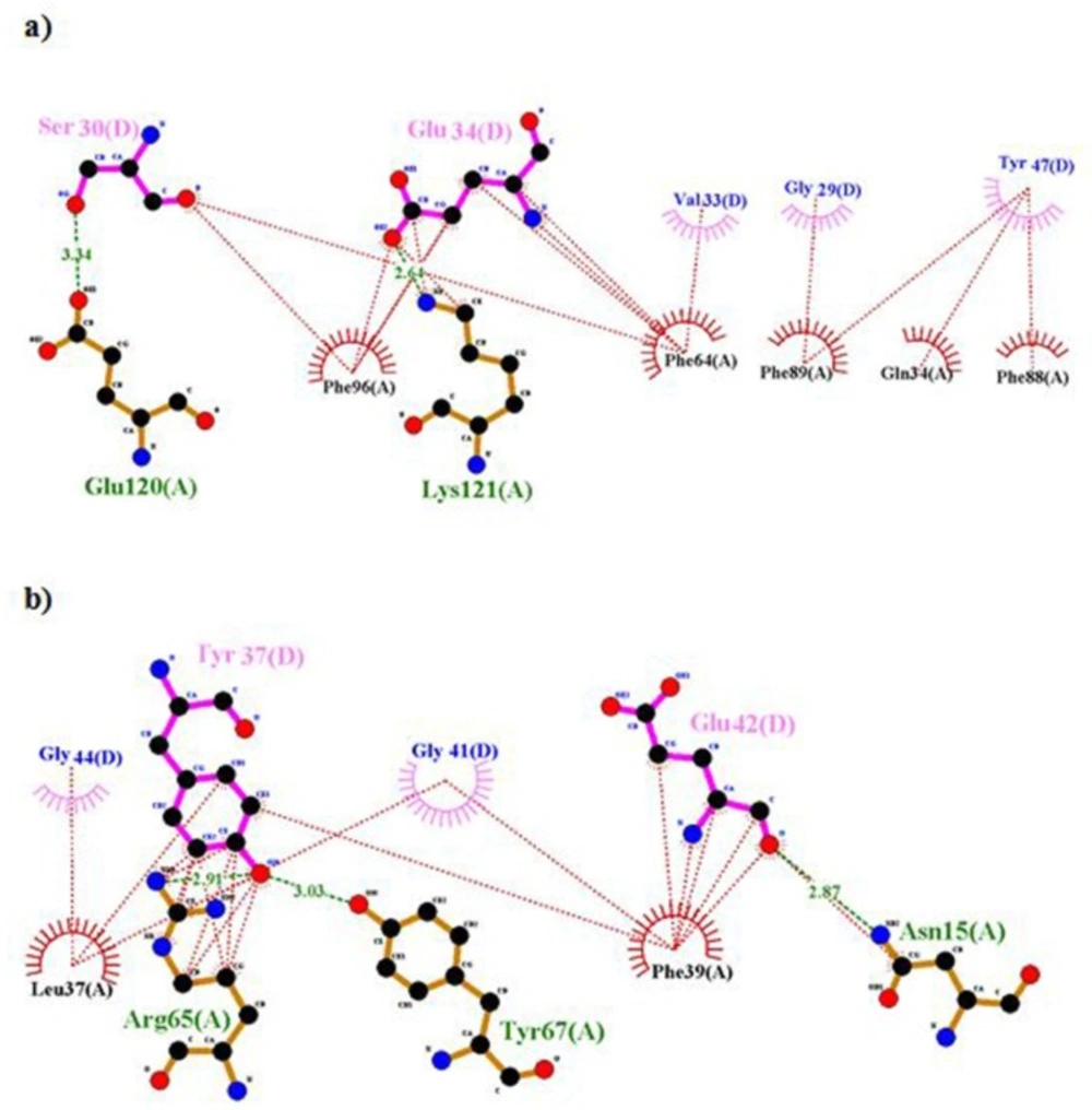
Ligplot representation of L1 and insulin. Output file of Ligplot represents hydrophobic interactions and hydrogen bonds between residues of rigid part 1 such as 34, 37, 39, 64, 65, 96, 88 and 89 with insulin; therefore they can’t interact with -CT
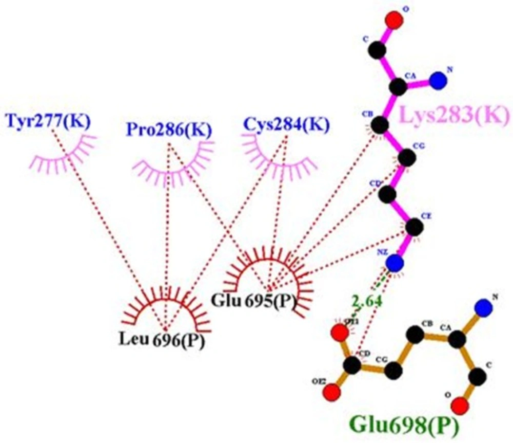
Ligplot representation of rigid part 3 of the first monomer and rigid part 3 of the second monomer. Residues 283, 4 and 286 of the first monomer interact with rigid part 3 of the second monomer; hence they prohibit the presence of residue 282 in the suitable interaction
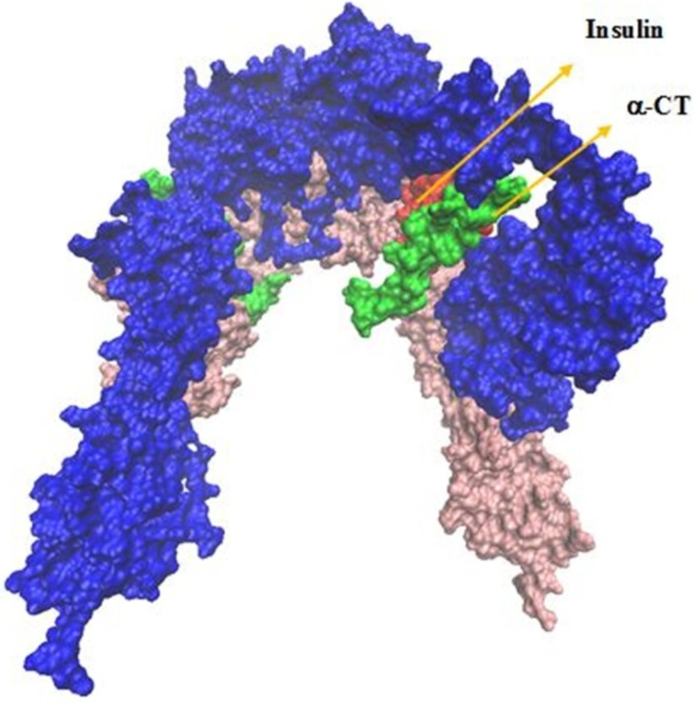
Representation of IR/insulin complex. Three residues of insulin, i.e., 44, 45, and 46 lie in the outside surface of L1, -CT and CR. They don’t hold into the volume between the CT segment, the L1– 2 surface and the adjacent CR domain
The extended beta sheet of secondary structures of insulin/IR complex is due to the formation of hydrogen bonds between protein atoms. Intracellular hydrogen bonds lead to be more stability in the protein structure (
28). Significant hydrogen bonds were created between different regions of IR and insulin. Rigid parts 2 and 3 domains of the second monomer have the major contribution in the hydrogen bond and hydrophobic interactions. Because of closing rigid part 3 to L1 domain of the first monomer and generation hydrophobic interaction and salt bridges between them, both regions contain notable hydrogen and hydrophobic interactions. Our data indicated that the secondary structure of protein became looser than turn and coil shape.
To survey the conformational change in residues Asn711-Val715 of α-CT, docking results were analyzed by Ligplot and stride server. Because of residues 711-715 are hydrophobic amino acids such as Val, Phe, and Asn, so when these residues interacted with hydrophilic residues of insulin like Tyr, Arg, Glu, and His, it causes to lie α-CT in a suitable position relative to insulin and they interact each other appropriately.
To evaluate the accuracy of constructed model, the resulted structure was compared with active sites obtained from Lawrence’s articles (
8,
12) (
Table 4). Comparing
Tables 4 with experimental results show that sequential docking method is a suitable approach to survey the interaction between two molecules because we applied additional information during the docking. This information included the order of components participation in docking processes to create a complex of insulin/IR dimer.
Our analysis in sequential docking showed input active sites of rigid part 4 of the first monomer participated in the interaction completely. Rigid part 4 of the second monomer interacted with insulin; rigid parts 1, 2 and 3 of the first monomer were compatible more than 80% with input data. Insulin was consistent with experimental data more than 60%. Illustration schematic of insulin/IR dimer by using sequential method has been represented in
Figure 7.
The origin of the difference between our model and experimental data are discussed in the following:
According to Lawrence’s articles (
8), hydrophobic face of α-CT comprising Phe705, Tyr708, Leu709, Val712 and Val713 engages a non-polar groove on L1β2 formed by Leu36, Leu37, Leu62, Phe64, Phe88, Phe89, Val94, and Phe96 (
8). But in our model, some of them, i.e., residues 36, 62 and 94 were not involved in the interaction. There are hydrophobic interactions and hydrogen bonds between residues of rigid part 1 such as 34, 37, 39, 65, 64, 96, 89, and 88 with insulin, so these residues have an affinity for insulin and they cannot interact with -CT (
Figure 8). But when residues of insulin, i.e., 30, 33, 34, 37, and 38 created hydrophobic interaction and hydrogen bond with rigid part 1, these residues prevented their neighbors, i.e., 31, 32, 35, 36, 39, and 40 to interact with rigid part 1. The same events happened for residue Asn282 in rigid part 3 of the first monomer. Residue 282 interacted with L1 of the first monomer (
8), but in our model, hydrophobic interaction and hydrogen bond between its around residues, i.e., 284, 283, and 286 with rigid part 3 of the second monomer prohibited the presence of residue 282 in the suitable interaction (
Figure 9).
In the experimental studies, situation and structural change of residues Gly44, Phe45, and Phe46 are unsolved (
8), but our results showed the interaction between residues 44-37, 45-14, 45-37, and 46-14, it makes to lie the mentioned residues of insulin in the outside surface of L1-β2, CR and α-CT (
Figure 10).
All output files resulting from HADDOCK have been shown in
Table 5. According to the results of this table, the number of non-polar (hydrophobic) and charge amino acids interacted with each other in the step 4 are more than its previous and next phases in the sequential docking method. So this step has the most electrostatic and VDW energy and also the lowest buried surface area relative to the whole processes. Since step 4 of sequential docking method has the most negative VDW and electrostatic energy, so we can conclude the interaction sites of this stage is stronger than other phases. Based on this result, previous steps involve in the initiation of interaction between insulin and its receptor, but step 4 leads to make a tight contact due to the highest electrostatic and VDW energy.